30
PRODUCT CARE
3. Loosen the jam nuts (b) at the rear left and right of the deck eyebolts (a) (Figure
46 on page 29).
4. Start at the rear right to raise the rear of the deck, tighten the upper jam nut (b)
to raise the deck or loosen the upper jam nut (b) to lower the rear of the deck
(Figure 46 on page 29).
5. Adjust the jam nut (b) at the rear left to take the “slack” out of the threaded rod
(Figure 46 on page 29).
6. Tighten both lower jam nuts (b) to secure the deck adjustment (Figure 46 on
page 29).
7. The final adjustment would be to take the “slack” out of the left rear linkage if
the rear of the deck was raised by adjusting the jam nuts (b) on the eyebolt (a).
Loosen the jam nuts (b) and tighten the upper jam nut (b) to remove “slack”
(Figure 46 on page 29).
8. In many cases it will be necessary to adjust deck height using both eyebolt
(a) adjustments and pitch adjustment to achieve the correct blade-to-ground
heights. If you remember that the front right blade tip adjustment is fixed and
you level to that height, adjusting the deck will be simplified (Figure 46 on
page 29).
Adjusting the Front Gauge Wheels
WARNING
Keep hands and feet away from the discharge opening of the cutting deck.
The front gauge wheels on the mower deck are an anti-scalp feature, and should not
ride on the ground. The front gauge wheels should be approximately 1/4-1/2” above
the ground when the deck is set in the desired height setting.
Using the deck lift handle, set the deck in the desired height setting, then check the
gauge wheel distance from the ground below. If necessary adjust the front gauge
wheels as follows:
1. Visually check the distance between the front gauge wheels and the ground. If
the gauge wheels are near or touching the ground, they should be raised. If more
than 1/2” above the ground, they should be lowered.
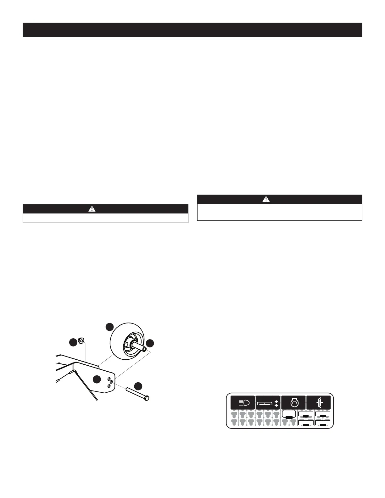
2. Remove the lock nut (a) securing one of the front gauge wheels (b) to the deck.
Remove the front gauge wheel (b), hex screw (c) and spacer (d) (Figure 47).
a
b
c
d
e
Figure 47
3. Insert the hex screw (c) into one of the three index holes in the front gauge wheel
bracket (e) that will give the front gauge wheel (b) a 1/4-1/2” clearance with the
ground (Figure 47).
4. Note the index hole of the just-adjusted front gauge wheel (b), and adjust the
other front gauge wheel (b) into the respective index hole of the other front
gauge wheel bracket (e) (Figure 47).
SERVICE
Charging the Battery
Test and, if necessary, recharge the battery after the mower has been stored for a
period of time.
MODELS WITH LEADACID BATTERY
• A lead-acid battery charger should be used. Recommended charge rate
is 5.5A/14.7V.
• If your battery charger is automatic, charge the battery until the charger indicates
that charging is complete. If the charger is not automatic, charge for no fewer
than eight (8) hours.
MODELS WITH AGM BATTERY
• An AGM battery charger should be used. Recommended charge rate is 1.1A/14.8V.
IMPORTANT! Do NOT use an automotive charger.
• If your battery charger is automatic, charge the battery until the charger indicates
that charging is complete. If the charger is not automatic, charge for no fewer
than eight (8) hours.
Jump Starting
WARNING
Failure to use this starting procedure can cause sparking, and the gases in
the battery to explode.
1. Connect one end of the red cable to the disabled mower battery’s positive
terminal; then connect the other end of that cable to the booster battery’s
positive terminal.
2. Connect one end of the black cable to the booster battery’s negative terminal;
then connect the other end of that cable to the frame of the disabled mower, as
far from the battery as possible.
3. Start the disabled mower following the normal starting instructions previously
provided; then disconnect the jumper cables in the exact reverse order of
their connection.
4. Have the mower’s electrical system checked and repaired as soon as possible to
eliminate the need for jump starting.
Electrical System (Relays & Fuses)
Fuses, relays and the breaker can be found by lifting the operator’s seat. The
fuses, relays and breaker are in the main power distribution module (PDM) to the
right of the battery (see Figure 48
†
for fuse layout and Figure 49 on page 31 for
assignments). These are standard mini type (ATM) plug-in automotive fuses. Always
use the same capacity fuse for replacement. If you have a recurring problem with
blown fuses, have the mower’s electrical system checked by an authorized service
dealer. See the Replacement Parts and Accessories section for relay and breaker
service part numbers.
R4
R1 R2 R3 R4
F1
F2
F4
-30-
B1
-15-
-25-
-10-
I29159A
F3
-30-
B1
R1
R2 R3
R4
F4 F1
F2F3
Figure 48
†
Fuse layout applies to SDL models only.

 Loading...