24 Section 4— Product care
Adjusting the Front Gauge Wheels
WARNING
Keep hands and feet away from the discharge opening
of the cutting deck.
The front gauge wheels on the mower deck are
an anti-scalp feature, and should not ride on
the ground. The front gauge wheels should be
approximately 1/4-1/2” above the ground when
the deck is set in the desired height setting.
Using the deck lift handle, set the deck in
the desired height setting, then check the
gauge wheel distance from the ground below.
If necessary adjust the front gauge wheels
as follows:
1. Visually check the distance between the
front gauge wheels and the ground. If
the gauge wheels are near or touching
the ground, they should be raised. If
more than 1/2” above the ground, they
should be lowered.
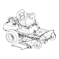
2. Remove the lock nut (a) securing one of
the front gauge wheels (b) to the deck.
Remove the front gauge wheel (b), hex
screw (c) and spacer (d). See Figure 4-12.
Figure 4-12
Note: There are a pair of front gauge
wheels on the nose of the 54” and
60” decks.
3. Insert the hex screw (c) into one of the
three index holes in the front gauge
wheel bracket (e) that will give the front
gauge wheel (b) a 1/4-1/2” clearance
with the ground. See Figure 4-12.
4. Note the index hole of the just adjusted
front gauge wheel (b), and adjust the
other front gauge wheel (b) into the
respective index hole of the other front
gauge wheel bracket (e). See Figure 4-12.
Service
Charging the Battery
Test and, if necessary, recharge the battery after
the tractor has been stored for a period of time.
Models with Lead-acid Battery
• A voltmeter or load tester should read
12.6 volts (DC) or higher across the
battery terminals. See Figure 4-13.
Figure 4-13
• Charge the battery with a 12-volt battery
charger at a MAXIMUM rate of 10 amps.
Voltmeter
Reading
State of
Charge
Charging
Time
12.7 100% Full Charge
12.4 75% 90 Min.
12.2 50% 180 Min.
12.0 25% 280 Min.
Models with AGM Battery
• An AGM Battery charger should be used.
Recommended charge rate is 1.1A/14.8V.
Note: Do NOT use an
automotive charger.
• If your battery charger is automatic,
charge the battery until the charger
indicates that charging is complete. If
the charger is not automatic, charge for
no fewer than eight (8) hours.
Jump Starting
WARNING
Failure to use this starting procedure can cause
sparking, and the gases in the battery to explode.
1. Connect the end of one cable to the
disabled machine battery’s positive
terminal; then connect the other end
of that cable to the booster battery’s
positive terminal.
2. Connect one end of the other cable to
the booster battery’s negative terminal;
then connect the other end of that cable
to the frame of the disabled tractor, as
far from the battery as possible.
3. Start the disabled tractor following the
normal starting instructions previously
provided; then disconnect the jumper
cables in the exact reverse order of
their connection.
4. Have the tractor’s electrical system
checked and repaired as soon as
possible to eliminate the need for
jump starting.
Servicing Electrical System
Fuse
There are two fuses located inside the left
console. Lift the seat and look down at the left
console to find the location of the fuses. One
30 amp fuse for the power steering and one
25 amp fuse the ignition, PTO, etc. These are
standard plug-in type automotive fuses. Always
use the same capacity fuse for replacement.
Check the 30 amp fuse if the power steering is
not working and check the 25 amp fuse for all
other electrical problems.
If you have a recurring problem with blown fuses,
have the tractor’s electrical system checked by
your authorized service dealer.
Safety Interlock System & Switch
Operation Checks
The following operational checks should be
made daily:
PTO Switch
1. Sit in the operator’s seat. With the drive
levers in the neutral position and the
parking brake engaged, engage the PTO
switch by pulling up on the knob and try
to start the engine. The engine should
not start. If it does, the PTO switch
must be replaced. See your authorized
service dealer.
2. If the engine does not start, disengage
the PTO by pressing the knob down and
start the engine. Now engage the PTO
and the blades should rotate.
3. If the blades do not turn, the PTO switch
must be replaced, the seat switch must
be replaced or the electric PTO clutch
must be repaired. See your authorized
service dealer.
Parking Brake Switch
1. Sit in the operator’s seat. With the drive
levers in the neutral position and the
PTO disengaged, release the parking
brake and try to start the engine. The
engine should not start.
2. If it does, the parking brake switch must
be repositioned or replaced. See your
authorized service dealer. If the engine
does not start, engage the parking brake
and start the engine.
Seat Switch
1. With the drive in the neutral position,
the parking brake engaged and the
PTO disengaged, start the engine. Now
release the parking brake and raise
up off the seat. Release the operator’s
seat and the engine should stop. If the
engine does not stop, the seat switch
must be replaced. See your authorized
service dealer.
2. With the drive in the neutral position,
the parking brake engaged and the PTO
disengaged, sit in the operator’s seat
and start the engine. Engage the PTO
and the blades should start to rotate.
Raise up slightly off the operator’s seat
and the blades should stop. If the blades
do not stop when you dismount from
the operator’s seat, the seat switch
must be replaced. See your authorized
service dealer.
Electric PTO Clutch
1. This clutch operates when the engine is
running, the operator is in the operator’s
seat and the PTO is engaged. This
electric clutch is a normally trouble free
device. If a problem develops and the
blades do not turn, first check the 25
amp fuse, then investigate the wiring
harness and the connections to the seat
switch, the PTO switch and the electric
blade clutch. Then check the seat switch,
the PTO switch and finally the electric
blade clutch. If the PTO clutch is still not
working properly, see an authorized
service dealer.
Rear Tire Removal/Replacement
1. Remove the four lug nuts (a) to remove
the tire. See Figure 4-14.
Figure 4-14
 Loading...