10 Section 2 — ASSembly & Set-Up
In the full reverse position,
• Control levers should not contact the
operator’s legs or torso.
Set the seat to the preferred operating position.
• Adjustment lever is located under the front
edge of the seat.
Check factory settings of control levers for the
conditions listed above.
NOTE: If control lever adjustments are required,
height adjustments should be made prior to
angular adjustments.
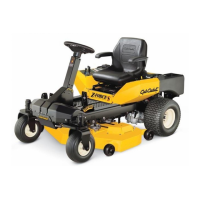
To adjust the height of the drive control levers:
1. Remove the flange lock nuts (a) that secure
the carriage bolts (b) in the drive control
levers. See Figure 2-4.
Figure 2-4
2. Remove the carriage bolts (b) from the drive
control levers and reposition to the second
set of holes in the mounting block.
3. Reinstall the carriage bolts (b) and flange lock
nuts (a), and tighten to 28-34 ft-lbs.
4. The same adjustments should be made to
both sides of the mower.
To adjust the front-to-rear angle of the drive
control levers:
1. Loosen the control lever knob (a) to unlock
the drive control levers. See Figure 2-5.
Figure 2-5
2. Move drive control levers to the desired
angle and retighten the drive control knob (a)
to secure the lapbars in place.
3. Check the results of any adjustments to the
conditions described above. Repeat any
adjustment procedures as required until all
conditions are met.
Operator’s Seat
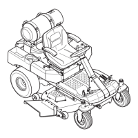
1. Remove the two flange lock nuts (b) and
shoulder bolts (a) from the manual bag. See
Figure 2-6.
Figure 2-6
2. Place the seat into position and secure the
seat into place with the hardware as shown in
Figure 2-6.
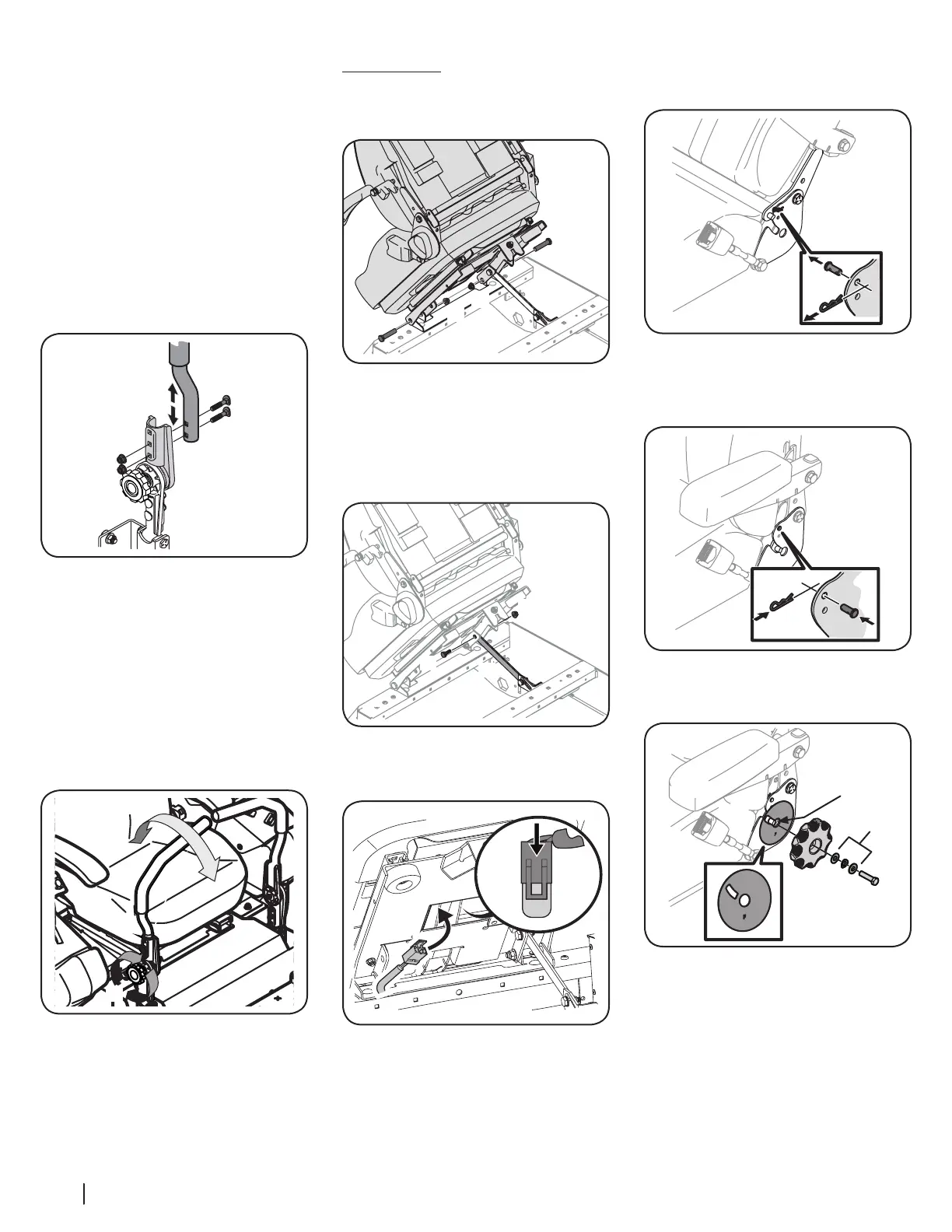
3. Remove the shoulder screw (a) and flange lock
nut (b) from manual bag and install the seat
lockout bracket (c) as shown in Figure 2-7.
Figure 2-7
4. Insert the wiring harness (a) into the bottom
of the seat as shown in Figure 2-8.
Figure 2-8
NOTE: When the wiring harness (a) is
connected, be sure to push the excess wire
from the wire harness (a) into the seat box
hole before continuing.
5. Remove the clevis pin (a) and cotter pin (b)
securing the recliner bearing plate in the
seat back position. See Figure 2-9.
Figure 2-9
6. Tilt the seat forward until the recliner
bearing plate (c) is below the clevis pin
(a) and then re-insert the cotter pin (b) to
secure the seat in place. See Figure 2-10.
Figure 2-10
7. Remove the seat tilt knob assembly from
the bag and install as shown in Figure 2-11.
Figure 2-11
NOTE: Be sure to orient the recliner bearing
plate (a) and install the washers (b) as shown
in Figure 2-11. The thicker washer is on the
outside.
8. Slide the recliner bearing plate (a) onto
the recliner pin (e). Then align the spiral on
the inside of the recliner knob (c) with the
recliner pin (e).
9. Use a wrench to hand tighten the hex screw (d)
until the recliner knob (c) is difficult to turn.
NOTE: Do not use power tools to install.
10. Gradually loosen the hex screw (d) until the
recliner knob moves freely. Do not loosen
the hex screw more than one full turn.
 Loading...