9Section 2 — ASSembly & Set-Up
Adjusting Drive Control Levers
The RH and LH drive control levers can be adjusted
up or down and fore-and-aft for the comfort of
the operator. Proper drive control lever and seat
adjustment will result in the following:
In the neutral position with hands on the
control levers,
• Operator’s upper arms should be relaxed
and approximately vertical.
• Operator’s forearms should be
approximately horizontal.
In the full forward position,
• Operator’s back should stay in contact with
the seat back.
• Control levers should not contact
operator’s legs.
In the full reverse position,
• Control levers should not contact the
operator’s legs or torso.
Set the seat to the preferred operating position.
• Adjustment lever is located under the front
edge of the seat.
Check factory settings of control levers for the
conditions listed above.
Note: If control lever adjustments are required,
height adjustments should be made prior to
angular adjustments.
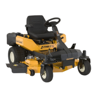
To adjust the height of the drive control levers:
1. Remove the flange lock nuts (a) that secure
the carriage bolts (b) in the drive control
levers. See Figure 2-5.
Figure 2-5
2. Remove the carriage bolts (b) from the drive
control levers and reposition to the second
set of holes in the mounting block. See
Figure 2-5.
3. Reinstall the carriage bolts (b) and flange
lock nuts (a), and tighten to 28-34 ft-lbs. See
Figure 2-5.
4. The same adjustments should be made to
both sides of the mower.
To adjust the front-to-rear angle of the drive
control levers:
1. Loosen the control lever knob (a) to unlock
the drive control levers. See Figure 2-6.
Figure 2-6
2. Move drive control levers to the desired
angle and retighten the drive control knob (a)
to secure the drive control levers in place.
3. Check the results of any adjustments to the
conditions described above. Repeat any
adjustment procedures as required until all
conditions are met.
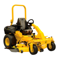
Operator’s Seat
1. Remove the two flange lock nuts (b) and
shoulder bolts (a) from the manual bag. See
Figure 2-7.
Figure 2-7
2. Place the seat into position and secure the
seat into place with the hardware as shown in
Figure 2-7.
3. Remove the shoulder screw (a) and flange lock
nut (b) from manual bag and install the seat
lockout bracket (c) as shown in Figure 2-8.
Figure 2-8
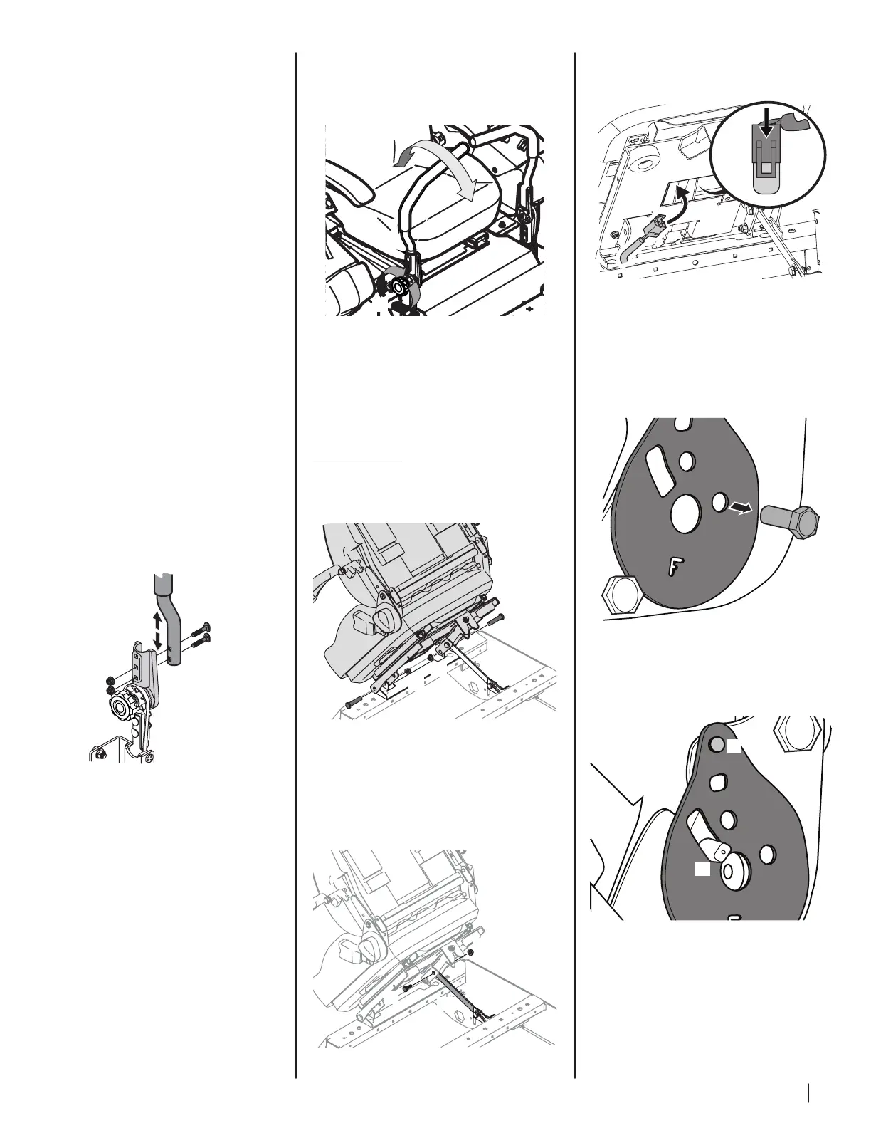
4. Insert the wiring harness (a) into the bottom
of the seat as shown in Figure 2-9.
Figure 2-9
Note: When the wiring harness (a) is
connected, be sure to push the excess wire
from the wire harness (a) into the seat box
hole before continuing.
5. Remove the screw (a) securing the recliner
plate in the seat back position. See Figure 2-10.
Figure 2-10
6. Tilt the seat forward into the full forward
position. Replace the recliner plate with
the clinch-stud (a) and the recliner pin (b)
passing through the recliner plate in the
locations shown in Figure 2-11.
Figure 2-11
 Loading...