Rev. -, p. 5 of 19
2. REAR MOUNT BRACKET
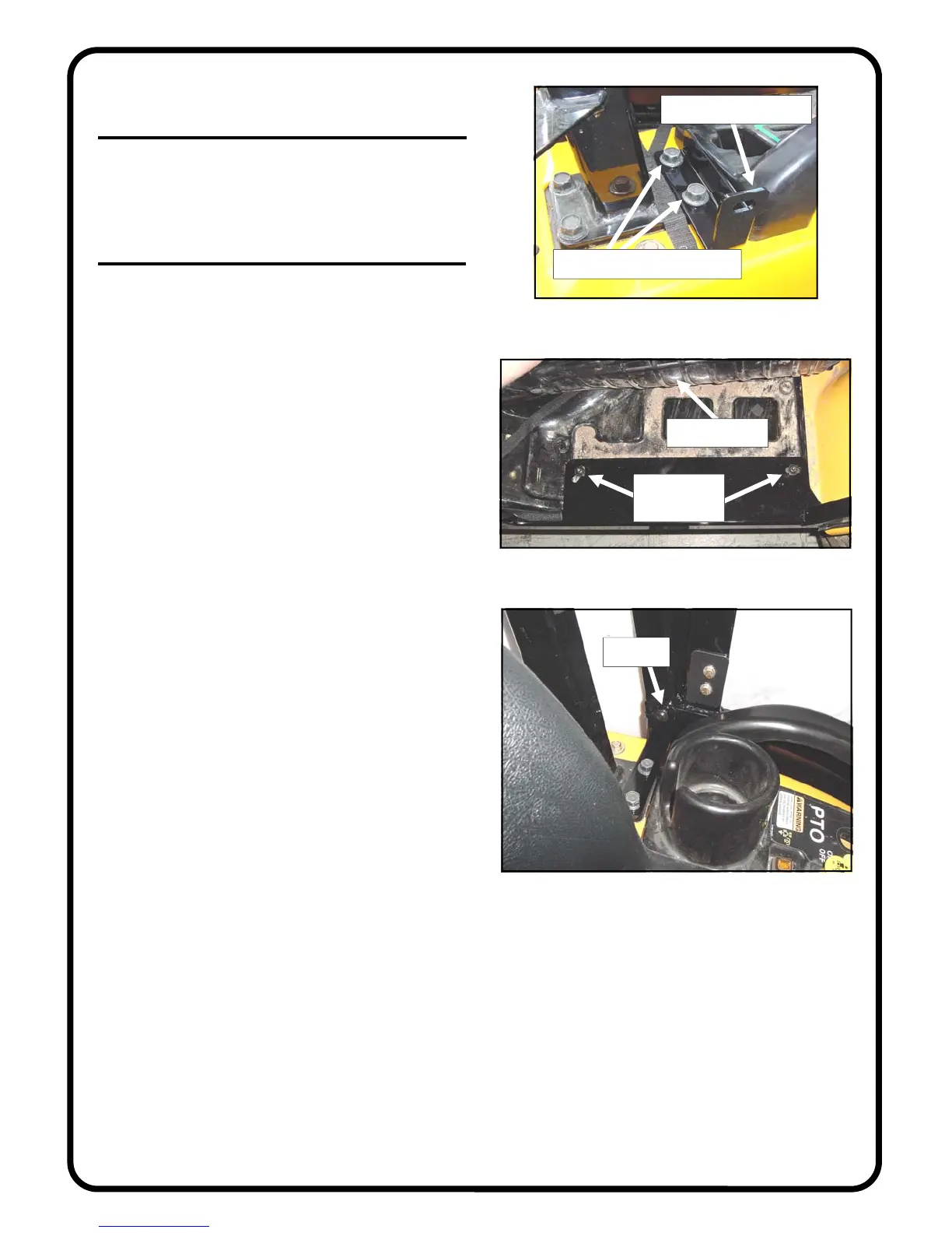
2.1 Per fig. 2.1, install the right side rear mount
bracket as shown with the notch pointing forward. Use
the two new, longer M12 bolts supplied. Leave bolts
loose. Repeat for opposite side..
Fig. 2.1 (view from right side)
notch to point forward
install two new, longer bolts
bolt here
Fig. 3.3 (view from inside the cab)
Fig. 3.2 (view from right side)
lift rubber mat
2 bolts and
washers here
3. SIDE FRAMES
3.1 For ease of handling, remove the door from the
side frame by lifting up and off the pin hinges that are
bolted to the side frame.
3.2 See fig. 3.2. With assistance, install the right side
frame to the tractor. The floorboard of the side frame is
to be underneath the rubber mat. Use a 5mm Allen
wrench and the following hardware per side: two M8
button head bolts and two steel washers. Note: these
thread into the original equipment weldnuts under the
tractor floorboard. Use caution to avoid cross threading
the weldnuts. Begin the thread engagement by hand.
Leave bolts loose. Repeat for opposite side.
3.3 Per fig. 3.3, install the following hardware through
the rear mount bracket and into factory installed threaded
inserts in the lower rear corners of the side frames: one
5/16-18 x 3/4” long button head bolt and one steel
washer. Leave bolt loose. Repeat for opposite side.
 Loading...