Rev. -, p. 7 of 19
6. ROLL BAR BRACKET
6.1 If installing an optional hard rear panel at this
time, skip to step 7 on the next page. (Note: the steel rear
mount shown in fig. 6.2 is not used with the optional
hard rear panel).
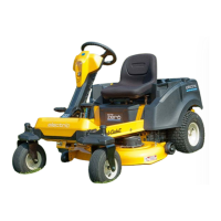
6.2 Per fig. 6.2, install the supplied rubber vibration
mount to the rear mount using the following hardware:
1/4-20 x 1” long button head bolt, one steel washer, and
one locknut. The head of the bolt is to be inside the re-
cess in the rubber. The washer is to be used on the lock-
nut side. Repeat for the other rear mount. Tighten these
bolts.
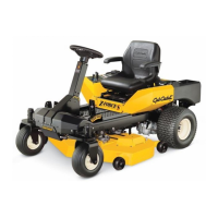
6.3 Per fig. 6.3, attach the rear mount to the back of
the side frame using the following hardware per side: two
5/16-18 x 3/4” long button head bolt and two steel wash-
ers into factory installed threaded inserts in the rear mid-
dle of the side frames. The rubber vibration mount is to
be up against the front face of the ROPS tubing. Leave
bolts loose. Repeat for the opposite side.
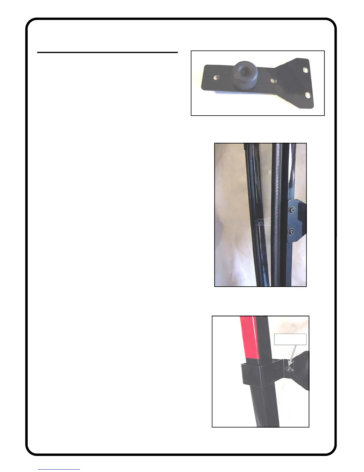
6.4 Per fig. 6.4, assemble the roll bar bracket to the
rear mount as shown. Use the following hardware: two
5/16-18 x 1” long button head bolts, 4 steel washers, and
two locknuts. The head of the bolts are to be towards the
rear of the tractor. Leave bolts loose. Repeat for opposite
side.
Fig. 6.3 (view from left rear side)
Fig. 6.2 (rear mount)
Fig. 6.4 (view from rear right side)
head of bolt
 Loading...