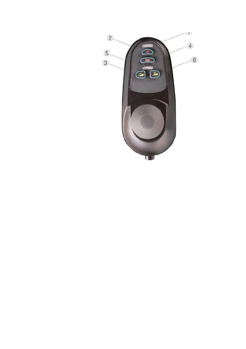
3 DECELERATION ADJUSTMENT SWITCH
4 Horn
5 speedometer
Fig. 6 controller function keys overlooking schematic diagram
Controller panel
Function description:
1 Battery Capacity Display
2 wheelchair power start switch
6 acceleration adjustment switch
(9). After the power is switched on, gent 1 y pull the controller lever in any direction to hear the electromagnetic
clutch sound and the motor rotation sound in the motor mechanism. The speed of the motor increases with the increase
of the range of the lever (the sound of the motor increases gradual 1 y) , and the speed of the motor (the sound of the
motor) will change when the lever is turned left or right, and the lever is released, the e 1 ectromagnetic c 1 utch will
release and make a noise, and the motor will stop.
⑩・ Close the motor clutch handle (so that the hand 1 e is paral lei to the wheel) , the operator sits on the vehicle,
turns on the power switch of the controller, and operates the vehicle, at whichtime the vehic1e moves with the