INSTALLATION WALKTHROUGH:
For more information log onto www.curtmfg.com, & for helpful towing tips log onto www.hitchinfo.com
T
R
I
M
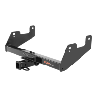
3. Enlarge rear-most hole on driver and passneger side to dimensions
shown on PAGE 1 to allow 1/2" carriage bolts, CM-SP6, and
CM-SP12 to pass into frame rails
7. Pull fascia down and raise hitch into position by sliding passenger side
plate under plastic tab as shown below.
8. Insert one (1) M8-1.25 x 30mm hex bolt with one (1) 5/16" lock washer
and one (1) 1/4" flat washer into weld nut where M8 bolt was removed in
STEP 2. Loosely secure remaining hardware with 1/2"-13 hex flange nuts.
4. Using trim diagram below, mark a 4.75" x 2.0" rectangle with masking
tape .75" away from edge of driver's side push button. Use this as a
guide for trimming. Trim marked area with rotary tool.
9. Reinstall push button fasteners and hex bolts removed
in STEP 1.
10. Torque all 1/2" hardware to 110 ft-lbs and all M8 hardware
to 22.9 ft-lbs.
.75 in
4.75 in
2.0 in
5. Using enlarged access holes, fishwire two (2) 1/2"-13 x 1 1/4" bolts and two (2)
CM-SP12 into two (2) forward-most holes in driver side frame rail.
Fishwire one (1) 1/2"-13 x 1 1/4" bolt and one (1) CM-SP12 in forward-most hole
into passenger side frame rail.
6. Reverse fishwire (1) one 1/2"-13 x 1 1/2" and (1) one CM-SP6 into each frame
rail using enlarged access hole.