INSTALLATION INSTRUCTIONS II11
Front
panel
Style may vary
Style may vary
Front
panel
Terminal
block
Terminal
block
Installation
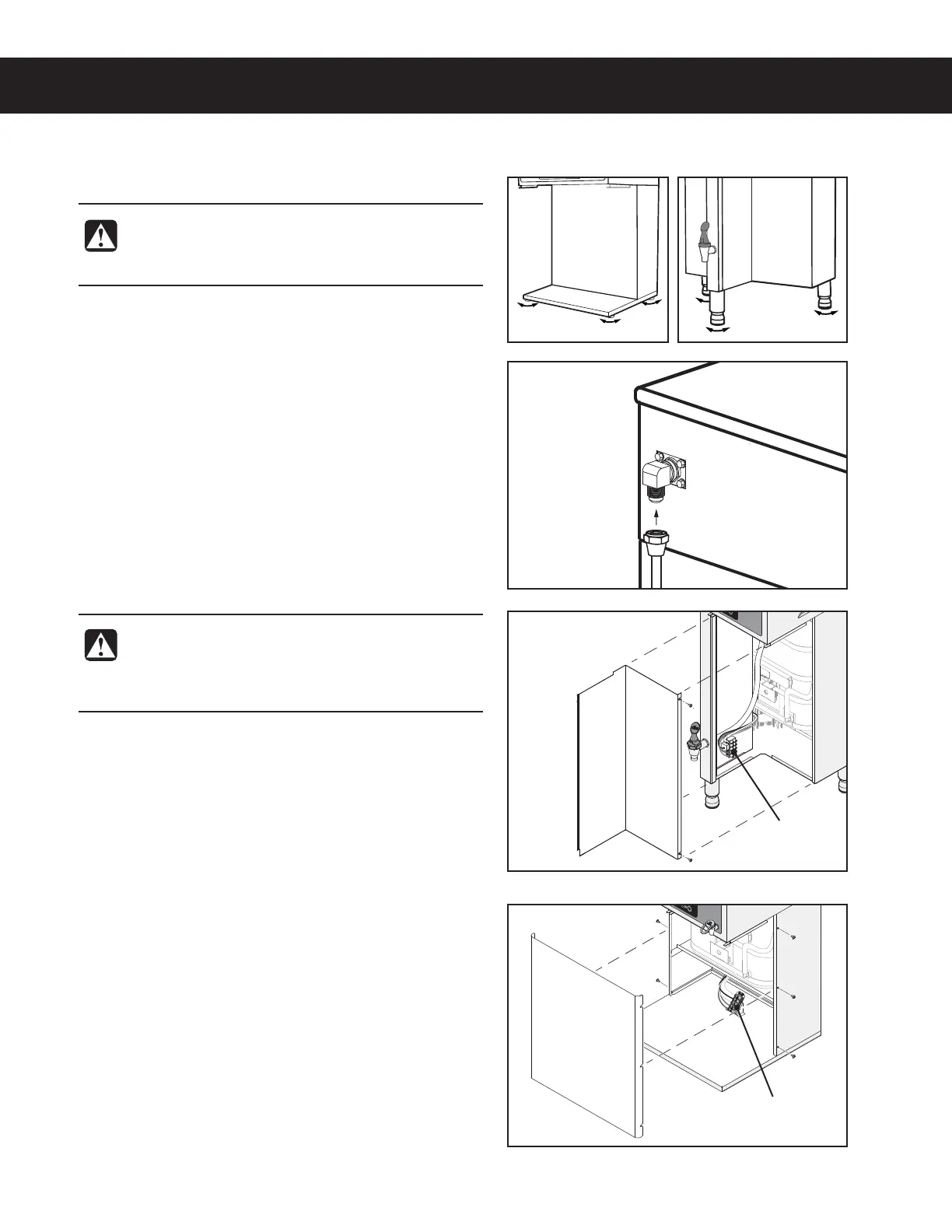
Leveling
1 Position the brewer on the counter top. Level it left to
right and front to back by turning the bottom of the
legs.
Connect the Water Supply
2 Flush the water supply line prior to installation to
QVSHFBJSBOEEFCSJTGSPNUIFXBUFSmMUFSBOEUVCJOH
3 $POOFDUUIFXBUFSTVQQMZMJOFUPUIFnBSFmUUJOHPO
the back of the brewer. Leave the water supply valve
closed until the power is connected.
Connecting the Power Cord (units without power cord
installed or units being converted from 120 Volt to 200
- 240 Volt operation)
4 Remove the screws that hold the front panel in place
and remove it.
5 Loosen the strain relief on the back of the brewer.
6
On units equipped with an existing 120 Volt power
cord, disconnect the cord from the terminal block
and remove it. Locate, disconnect and cap the
jumper wire between the “C” and “N” terminals on the
terminal block.
7 Feed the end of the power cable, through the strain
relief and into the unit and connect it to the power
block according to the ELECTRICAL SCHEMATIC.
8
Tighten the strain relief and r
eplace the front panel.
9
If a power plug will not be used, connect the power
cable wires dir
ectly to the terminals in the junction
box. See the ELECTRICAL SCHEMATIC for the power
supply requirements.
WARNING: Use the leveling legs to level the
brewer only. Do not use them to adjust brewer
height. Do not extend them higher than necessary.
WARNING: Turn off power to the circuit at the
circuit breaker panel before connecting the power
cable to the brewer. Lock out and tag the circuit
breaker.
(5)&3.0130.*-"/0*/45"--"5*0/*/4536$5*0/4ø 092519E
TPX2, TP2 and TPC2 Series
TPX1 and TP1 Series
 Loading...