www.cuttermasters.com - Toll Free (800) 417 2171
CUTTERMASTER Professional JXT User’s Manual
Page 7
B
C
D
SHEET 1 OF 1
DRAWN
CHECKED
APPROVED
Jeff
DWG NAME
2020 SINGLE UTS Front Side
TITLE
Cuttermaster Professional DC Tower
SIZE
C
REV
3
Toycen
This document is the property of Toycen and cannot be copied or reproduced in full or in
part or communicated to third parties without specific written permission from Toycen.
UNLESS OTHERWISE SPECIFIED:
DRAWINGS ARE IN INCHES (mm).
DATE
SCALE:
LINEAR TOLERANCES ANGLES ARE:
ARE: .X =
± .03 X = ± 0.5°
.XX = ± .01 .X = ± 0.1°
.XXX = ± .005
SURFACE FINISH:
DO NOT SCALE DRAWING
125
THIRD ANGLE
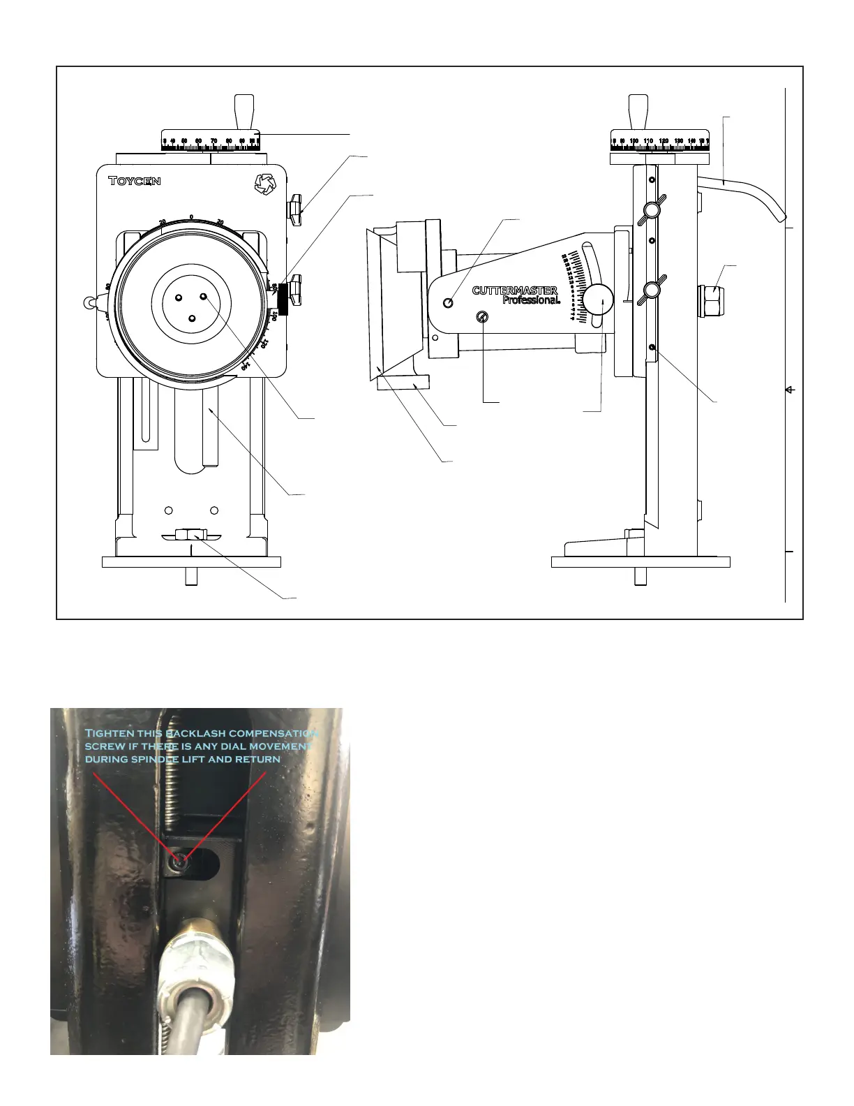
10-32 WHeel Cap Bolts
Operation Gib Clamp thumb screws
90 Degree Spring ball
Up 22 Down 7 Motor Tilt lock
Remove this to tilt the motor into the 890 degree Position
End grinds withnthe face of the wheel
Multi Position Wheel guards in 5 and 6 inch
Gib tension set screws(3)
Motor Tilt Rotate
Tension Setting
Motor Vertical Lift
Indexing Handle
Acme 10 Lead screw with backlash
and rotational tension adjustment
Table Clamp bolt 3/8-16
Vertical Travel Hand Dial
Standard 1-1/4 Tool Grinder wheel hub
Oillite Bushed Motor tilt with
Ratchet Lever angle Locks
Notes:Vertical Slide assembly gib must be
tensioned so the it is tight but free to travel ,dove tail assemblies are lapped
and should travel freely when adjusted.
Minor deflections are normal Tighten thumb screwswhile in use for the best
grinding finishes
Whenyou’reindexingtothenextutebetweengrinds,
the tool needs to be clear of the grinding wheel. To
do so, you have the choice of rocking the air spindle
towards you, or using the Motor Vertical Lift Indexing
Handle. When using the motor lift handle, if you notice
that the motor isn’t returning consistently, try tightening
the backlash compensation screw.
z-Axis Backlash Compensator: