EasyManua.ls Logo

CyberPower 14/351mm - User Manual

CyberPower 14/351mm
2 pages
Print Icon
To Next Page IconTo Next Page
Loading...
Relay Control Card
RELAYIO500
Relay Control Card
RELAYIO500
User’s Manual
K01-0000416-01
Internal Circuit
RELAYIO500 Card Pinout
Pin
Assignment
Function I/O
Pin1 UPS FAULT O/P
Pin2 SUMMARY ALARM O/P
Pin3 GND (Common for Pin4) Power GND
Pin4 REMOTE SHUTDOWN Power + Vcc
Pin5 COMMON (For Relays) O/P
Pin6 BYPASS
1
/ UPS OFF O/P
Pin7 BATTERY LOW O/P
Pin8 UPS ON O/P
Pin9 UTILITY LINE FAIL O/P
Note: All relay contacts are normally open (N.O.) except for Pin6.
Acceptable Power + Vcc for Pin4 is 7.5 – 12V, 0.0672W Max.
1
For OL series UPS models only
1
6
2
7
3
4
5
8
9
UPS FAULT
SUMMARY ALARM
GND (Common for Pin4)
REMOTE SHUTDOWN
COMMON (For Relays)
BYPASS
1
/ UPS OFF
BATTERY LOW
UPS ON
UTILITY LINE FAIL
GND
Overview
The CyberPower Relay Control Card (RELAYIO500) offers users the
solution for UPS status monitoring via 5 output relays. In addition, the
RELAYIO500 card provides 1 input contact to perform UPS shutdown in
battery mode. This card is compatible with most CyberPower UPS devices
with expansion slot.
Installation Guide
The RELAYIO500 card is hot-swappable and can be installed while the
UPS is on.
1. Remove the two retaining screws on the expansion slot cover, and then
remove the cover.
2. Install the CyberPower RELAYIO500 card into the expansion slot.
3. Re-install and tighten the retaining screws.
Technical Specifications
RELAYIO500
Electrical
External S/D Voltage 7.5V – 12V
Power Dissipation
1.35W Max
(Default 12V input)
Physical
Dimensions (WxHxD)
41.8 x 14.2 x 81mm
(1.65 x 0.6 x 3.2 in)
Weight 52g (1.92oz)
Environmental
Operating Temperature 0°C – 40°C (32°F - 104°F)
Operating Humidity 0% – 95% (Non-condensing)
Output Relay Rating
Maximum
Voltage Current
30VDC / 125VAC 3A (per relay)
Function Description
Status Condition
Pin1 short to Pin5
UPS fault (Inverter Fault / DC Bus Fault / Over
Temperature / Output Short / Battery Over Charge /
Battery Test Fail
1
/ Fan Error
1
)
Pin2 short to Pin5
Summary alarm (Inverter Fault / DC Bus Fault /
Output Short / Over Temperature / Over Load /
Battery Missing / Battery Over Charge / Battery Low /
Wiring Fault / Runtime Low
2
/ Battery Test Fail
1
/
Load Over Setting Level
1
/ Fan Error
1
)
Pin6 short to Pin5 UPS is OFF. / UPS is in Bypass Mode.
1
Pin7 short to Pin5 Battery Low
Pin8 short to Pin5 UPS is on.
Pin9 short to Pin5 Utility Line Fail
1
For OL series UPS models only
2
For PR/OR series UPS models only
Example Application
Supply 12VDC to the COMMON contact and connect LEDs to the DB-9
port pins 1, 2 and 6 to 9. Connect a push button to COMMON (Pin5) and
REMOTE SHUTDOWN (Pin4). Pressing the button for at least 5 seconds
will shutdown the UPS when it is on battery.
Note: When the UPS is on battery, the REMOTE SHUTDOWN input (Pin4
& Pin3) accepts at least 5 seconds of high level signal (+12VDC) to perform
the UPS shutdown. UPS output power will turn off after 120 seconds.
1
6
2
7
3
4
5
8
9
UPS FAULT
SUMMARY ALARM
GND (Common for Pin4)
REMOTE SHUTDOWN
COMMON (For Relays)
BYPASS
1
/ UPS OFF
BATTERY LOW
UPS ON
UTILITY LINE FAIL
12V
Question and Answer IconNeed help?

Do you have a question about the CyberPower 14/351mm and is the answer not in the manual?

Overview

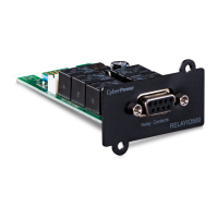
The CyberPower RELAYIO500 Relay Control Card is a device designed for UPS status monitoring and control, offering a solution for integrating UPS systems with external monitoring and control systems. It provides five output relays for status indication and one input contact for initiating UPS shutdown.

Function Description

The RELAYIO500 card utilizes a DB-9 connector with nine pins, each assigned a specific function for input/output (I/O) operations. All relay contacts are normally open (N.O.) except for Pin6. The acceptable power input for Pin4 (REMOTE SHUTDOWN) is 7.5V-12V, with a maximum power dissipation of 0.0672W.

The card's functionality is detailed through the status of short circuits between specific pins:

  • Pin1 short to Pin5 (UPS FAULT): Indicates various UPS fault conditions such as Inverter Fault, DC Bus Fault, Over Temperature, Output Short, Battery Over Charge, Battery Test Fail (for OL series UPS models only), or Fan Error (for OL series UPS models only).
  • Pin2 short to Pin5 (SUMMARY ALARM): Triggers a summary alarm for a range of issues including Inverter Fault, DC Bus Fault, Output Short, Over Temperature, Over Load, Battery Missing, Battery Over Charge, Battery Low, Wiring Fault, Runtime Low (for PR/OR series UPS models only), Battery Test Fail (for OL series UPS models only), Load Over Setting Level (for OL series UPS models only), or Fan Error (for OL series UPS models only).
  • Pin6 short to Pin5 (BYPASS / UPS OFF): Indicates that the UPS is OFF or the UPS is in Bypass Mode (for OL series UPS models only).
  • Pin7 short to Pin5 (BATTERY LOW): Signals a low battery condition.
  • Pin8 short to Pin5 (UPS ON): Indicates that the UPS is currently operating.
  • Pin9 short to Pin5 (UTILITY LINE FAIL): Signals a failure in the utility line power.

The REMOTE SHUTDOWN input (Pin4) works in conjunction with Pin3 (GND). When the UPS is on battery, a high-level signal (+12VDC) applied to Pin4 for at least 5 seconds will initiate a UPS shutdown. The UPS output power will turn off after 120 seconds following this signal.

Important Technical Specifications

Electrical:

  • External S/D Voltage: 7.5V - 12V
  • Power Dissipation: 1.35W Max (Default 12V input)
  • Output Relay Rating:
    • Voltage: 30VDC / 125VAC
    • Maximum Current: 3A (per relay)

Physical:

  • Dimensions (WxHxD): 41.8 x 14.2 x 81mm (1.65 x 0.6 x 3.2 in)
  • Weight: 52g (1.92oz)

Environmental:

  • Operating Temperature: 0°C - 40°C (32°F - 104°F)
  • Operating Humidity: 0% - 95% (Non-condensing)

Usage Features

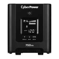
The RELAYIO500 card is compatible with most CyberPower UPS devices that feature an expansion slot. An example application demonstrates how to use the card for both status monitoring and remote shutdown. By supplying 12VDC to the COMMON contact (Pin5) and connecting LEDs to pins 1, 2, and 6 through 9, users can visually monitor various UPS statuses. For remote shutdown, a push button connected between COMMON (Pin5) and REMOTE SHUTDOWN (Pin4) can be used. Pressing this button for at least 5 seconds when the UPS is on battery will initiate a shutdown.

Maintenance Features

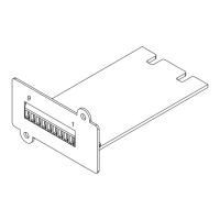
The RELAYIO500 card is designed for ease of installation and maintenance. It is hot-swappable, meaning it can be installed or removed while the UPS is operating. The installation process involves:

  1. Removing the two retaining screws and the cover of the expansion slot.
  2. Inserting the CyberPower RELAYIO500 card into the expansion slot.
  3. Re-installing and tightening the retaining screws.

This hot-swappable feature minimizes downtime and simplifies maintenance procedures.

CyberPower 14/351mm Specifications

General IconGeneral
Nominal input voltage230 V
Input frequency50/60 Hz
Output current16 A
Input Voltage230 V
Maximum Load Current16 A
Operating Temperature0 - 45 °C
Humidity0 - 95%

Related product manuals