EasyManua.ls Logo

CyberPower RELAYIO501 - User Manual

CyberPower RELAYIO501
2 pages
Print Icon
To Next Page IconTo Next Page
Loading...
Relay Control Card
RELAYIO50
9
Relay Control Card
RELAYIO50
1
User’s Manual
1
K01-0000531-00
Internal Circuit
RELAYIO501 Card Pinout
Pin
Assignment
Function I/O
Pin1 UPS FAULT O/P
Pin2 SUMMARY ALARM O/P
Pin3 GND (Common for Pin4) Power GND
Pin4 REMOTE SHUTDOWN Power + Vcc
Pin5 COMMON (For Relays) O/P
Pin6 BYPASS
1
/ UPS OFF O/P
Pin7 BATTERY LOW O/P
Pin8 UPS ON O/P
Pin9 UTILITY LINE FAIL O/P
Note: All relay contacts are normally open (N.O.) except for Pin6.
Acceptable Power + Vcc for Pin4 is 7.5 – 12V, 0.0672W Max.
1
For OL series UPS models only
BYPASS
1
/ UPS OFF
BATTERY LOW
UPS ON
UTILITY LINE FAIL
1
6
2
7
3
4
5
8
9
UPS FAULT
SUMMARY ALARM
GND (Common for Pin4)
REMOTE SHUTDOWN
COMMON (For Relays)
GND
Overview
The CyberPower Relay Control Card (RELAYIO501) offers users the
solution for UPS status monitoring via 5 output relays. In addition, the
RELAYIO501 card provides 1 input contact to perform UPS shutdown in
battery mode. This card is compatible with most CyberPower UPS devices
with expansion slot.
Installation Guide
The RELAYIO501 card is hot-swappable and can be installed while the
UPS is on.
1. Remove the two retaining screws on the expansion slot cover, and then
remove the cover.
2. Install the CyberPower RELAYIO501 card into the expansion slot.
3. Re-install and tighten the retaining screws.
Technical Specifications
RELAYIO501
Electrical
External S/D Voltage 7.5V – 12V
Power Dissipation
1.35W Max
(Default 12V input)
Physical
Dimensions (WxHxD)
41.8 x 14.2 x 81mm
(1.65 x 0.6 x 3.2 in)
Weight 52g (1.92oz)
Environmental
Operating Temperature 0°C – 40°C (32°F - 104°F)
Operating Humidity 0% – 95% (Non-condensing)
Output Relay Rating
Maximum
Voltage Current
30VDC / 125VAC 3A (per relay)
Function Description
Status Condition
Pin1 short to Pin5
UPS fault (Inverter Fault / DC Bus Fault / Over
Temperature / Output Short / Battery Over Charge /
Battery Test Fail
1
/ Fan Error
1
)
Pin2 short to Pin5
Summary alarm (Inverter Fault / DC Bus Fault /
Output Short / Over Temperature / Over Load /
Battery Missing / Battery Over Charge / Battery Low /
Wiring Fault / Runtime Low
2
/ Battery Test Fail
1
/
Load Over Setting Level
1
/ Fan Error
1
)
Pin6 short to Pin5 UPS is OFF. / UPS is in Bypass Mode.
1
Pin7 short to Pin5 Battery Low
Pin8 short to Pin5 UPS is on.
Pin9 short to Pin5 Utility Line Fail
1
For OL series UPS models only
2
For PR/OR series UPS models only
Question and Answer IconNeed help?

Do you have a question about the CyberPower RELAYIO501 and is the answer not in the manual?

Overview

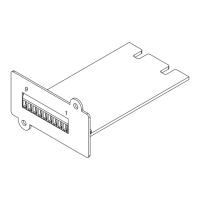
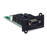
The CyberPower Relay Control Card (RELAYIO501) is a versatile accessory designed to enhance the monitoring and control capabilities of CyberPower Uninterruptible Power Supply (UPS) devices equipped with an expansion slot. This card provides a robust solution for users seeking to integrate UPS status information into external systems and to implement remote shutdown functionalities.

Function Description

The RELAYIO501 card primarily serves two main functions:

  1. UPS Status Monitoring via Output Relays: The card features five output relays that provide real-time status updates of the connected UPS. These relays act as dry contacts, allowing for easy integration with various external monitoring systems, building management systems, or custom control circuits. Each relay corresponds to a specific UPS status, providing clear and actionable information.

    • UPS Fault (Pin1 short to Pin5): This relay activates when the UPS experiences a critical fault, such as an inverter fault, DC bus fault, over temperature, output short, battery overcharge, battery test failure, or fan error. This comprehensive fault reporting ensures that critical issues are immediately flagged.
    • Summary Alarm (Pin2 short to Pin5): This relay provides a consolidated alarm for a range of UPS conditions, including inverter fault, DC bus fault, output short, over temperature, overload, missing battery, battery overcharge, battery low, wiring fault, low runtime, battery test failure, load over setting level, or fan error. This summary alarm offers a quick overview of any non-optimal operational state.
    • Bypass / UPS Off (Pin6 short to Pin5): This relay indicates when the UPS is either turned off or operating in bypass mode. This is particularly useful for understanding the power path and ensuring that the load is protected. For specific OL series UPS models, this relay specifically indicates bypass mode.
    • Battery Low (Pin7 short to Pin5): This relay activates when the UPS battery charge falls below a predefined threshold, signaling the need for intervention or graceful system shutdown to prevent data loss.
    • UPS On (Pin8 short to Pin5): This relay indicates that the UPS is actively providing power to the connected load, confirming normal operation.
    • Utility Line Fail (Pin9 short to Pin5): This relay activates when the main utility power supply is interrupted or falls outside acceptable parameters, indicating that the UPS is operating on battery power.
  2. Remote Shutdown Capability: The RELAYIO501 card includes one input contact (Pin4 and Pin3) that allows for remote shutdown of the UPS when it is operating on battery power. By applying a high-level signal (7.5-12VDC) for at least 5 seconds to this input, users can initiate a controlled shutdown of the UPS, which will turn off the UPS output power after 120 seconds. This feature is crucial for managing power in remote or automated environments, ensuring orderly system shutdowns during extended power outages.

Usage Features

The RELAYIO501 card is designed for ease of integration and practical application in various scenarios:

  • Dry Contact Outputs: The relay contacts are normally open (N.O.), providing flexibility for connection to different types of external systems without requiring complex interface circuitry. The common pin for the relays (Pin5) simplifies wiring for multiple status indicators.
  • Remote Monitoring: By connecting LEDs or other indicators to the output relays, users can visually monitor the UPS status from a distance. For example, an LED connected between a status pin (e.g., Pin1 for UPS Fault) and the common pin (Pin5) will illuminate when the corresponding status is active.
  • Automated Control: The relay outputs can be integrated with programmable logic controllers (PLCs), building management systems (BMS), or other automation platforms to trigger specific actions based on UPS status. For instance, a "Battery Low" signal could initiate a graceful shutdown of connected servers, while a "UPS Fault" signal could alert maintenance personnel.
  • Remote Shutdown Implementation: The remote shutdown input allows for controlled power management. In an example application, a push button connected between the common pin (Pin5) and the remote shutdown pin (Pin4) can be used to manually initiate a UPS shutdown. This is particularly useful for ensuring data integrity during prolonged power outages when the UPS is operating on battery.
  • Compatibility: The card is compatible with most CyberPower UPS devices that feature an expansion slot, making it a versatile addition to existing UPS infrastructures.

Maintenance Features

The RELAYIO501 card is designed with user-friendliness and ease of maintenance in mind:

  • Hot-Swappable Design: A significant advantage of the RELAYIO501 card is its hot-swappable capability. This means the card can be installed or removed while the UPS is operational, minimizing downtime and disruption to critical loads. This feature is invaluable for maintaining continuous power in sensitive environments.
  • Simple Installation Process: The installation procedure is straightforward, requiring only a few steps:
    1. Remove the two retaining screws and the cover from the UPS expansion slot.
    2. Insert the RELAYIO501 card into the expansion slot.
    3. Re-install and tighten the retaining screws to secure the card in place. This simple process ensures quick deployment and reduces the need for specialized tools or extensive technical expertise.
  • Robust Construction: The card is built to withstand typical operating environments, with a design that ensures reliable performance over time. The physical dimensions are compact, allowing it to fit seamlessly into the UPS expansion slot without adding bulk.

In summary, the CyberPower Relay Control Card (RELAYIO501) offers an effective and reliable solution for extending the monitoring and control capabilities of compatible CyberPower UPS systems. Its comprehensive status reporting, remote shutdown functionality, and user-friendly design make it an essential tool for enhanced power management and system integration.

CyberPower RELAYIO501 Specifications

General IconGeneral
ModelRELAYIO501
Output5 relay outputs
Relay ControlDry contact
ProtocolsSNMP
Operating Temperature0°C to 40°C
Operating Humiditynon-condensing
Dimensions4.53" x 3.54" x 1.18" (115 x 90 x 30 mm)

Related product manuals