1
User’s Manual
K01-0000531-00
Internal Circuit
RELAYIO501 Card Pinout
Pin
Assignment
Function I/O
Pin1 UPS FAULT O/P
Pin2 SUMMARY ALARM O/P
Pin3 GND (Common for Pin4) Power GND
Pin4 REMOTE SHUTDOWN Power + Vcc
Pin5 COMMON (For Relays) O/P
Pin6 BYPASS
1
/ UPS OFF O/P
Pin7 BATTERY LOW O/P
Pin8 UPS ON O/P
Pin9 UTILITY LINE FAIL O/P
Note: All relay contacts are normally open (N.O.) except for Pin6.
Acceptable Power + Vcc for Pin4 is 7.5 – 12V, 0.0672W Max.
1
For OL series UPS models only
BYPASS
1
/ UPS OFF
BATTERY LOW
UPS ON
UTILITY LINE FAIL
1
6
2
7
3
4
5
8
9
UPS FAULT
SUMMARY ALARM
GND (Common for Pin4)
REMOTE SHUTDOWN
COMMON (For Relays)
GND
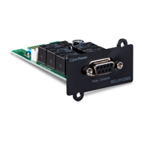
Overview
The CyberPower Relay Control Card (RELAYIO501) offers users the
solution for UPS status monitoring via 5 output relays. In addition, the
RELAYIO501 card provides 1 input contact to perform UPS shutdown in
battery mode. This card is compatible with most CyberPower UPS devices
with expansion slot.
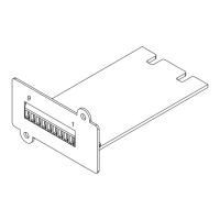
Installation Guide
The RELAYIO501 card is hot-swappable and can be installed while the
UPS is on.
1. Remove the two retaining screws on the expansion slot cover, and then
remove the cover.
2. Install the CyberPower RELAYIO501 card into the expansion slot.
3. Re-install and tighten the retaining screws.
Technical Specifications
RELAYIO501
Electrical
External S/D Voltage 7.5V – 12V
Power Dissipation
1.35W Max
(Default 12V input)
Physical
Dimensions (WxHxD)
41.8 x 14.2 x 81mm
(1.65 x 0.6 x 3.2 in)
Weight 52g (1.92oz)
Environmental
Operating Temperature 0°C – 40°C (32°F - 104°F)
Operating Humidity 0% – 95% (Non-condensing)
Output Relay Rating
Maximum
Voltage Current
30VDC / 125VAC 3A (per relay)
Function Description
Status Condition
Pin1 short to Pin5
UPS fault (Inverter Fault / DC Bus Fault / Over
Temperature / Output Short / Battery Over Charge /
Battery Test Fail
1
/ Fan Error
1
)
Pin2 short to Pin5
Summary alarm (Inverter Fault / DC Bus Fault /
Output Short / Over Temperature / Over Load /
Battery Missing / Battery Over Charge / Battery Low /
Wiring Fault / Runtime Low
2
/ Battery Test Fail
1
/
Load Over Setting Level
1
/ Fan Error
1
)
Pin6 short to Pin5 UPS is OFF. / UPS is in Bypass Mode.
1
Pin7 short to Pin5 Battery Low
Pin8 short to Pin5 UPS is on.
Pin9 short to Pin5 Utility Line Fail
1
For OL series UPS models only
2
For PR/OR series UPS models only