The CYBERTEK HCP8000 series current probes are advanced DC/AC active current probes designed for accurate and high-bandwidth current measurements. These probes are engineered to capture current waveforms with high fidelity, offering an accuracy of up to 1% and minimal circuit insertion loss. They are compatible with any oscilloscope equipped with a high-impedance BNC input, making them versatile tools for various electronic testing and measurement applications.
Function Description
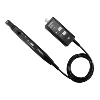
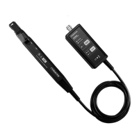
The core function of the HCP8000 series probes is to measure both direct current (DC) and alternating current (AC) across a wide frequency range. This capability is crucial for analyzing complex power systems and electronic circuits where both DC and AC components are present. The probes utilize a sensor head, which is the critical component containing a precise semiconductor. This sensor head clamps around a conductor to non-invasively measure the current flowing through it. The measured current is then converted into a voltage signal that can be displayed and analyzed by an oscilloscope.
A key feature is the ability to select between high and low current ranges, allowing for precise measurements across a broad spectrum of current magnitudes. For instance, the HCP8030 model offers both 30A and 5A ranges, while the HCP8150 provides 150A and 30A options, and the HCP8300 offers 300A and 50A ranges. This flexibility ensures that users can achieve optimal resolution and accuracy for different measurement scenarios, from low current measurements to higher power applications.
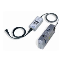
The probes also incorporate an overload protection system, which is indicated by dual indicators: a buzzer and an LED. If the current being measured exceeds the probe's specified limit, the red LED will illuminate, and an audible alarm will sound, alerting the user to a potentially damaging condition. This safety feature helps prevent damage to both the probe and the circuit under test.
Usage Features
The HCP8000 series probes are designed for user-friendly operation, incorporating several features to enhance ease of use and measurement reliability.
- Degaussing and Automatic Zero Setting: Frequent use or exposure to strong magnetic fields can lead to residual magnetism in the probe's core, affecting measurement accuracy. To counteract this, the probes feature a degaussing and auto-zero button. Pressing this button initiates a process that demagnetizes the core and sets the output to zero voltage, ensuring accurate DC measurements. This process typically takes a few seconds and is indicated by a green LED and short beeps upon successful completion. It is crucial to perform degaussing and zero setting before each measurement, especially without any current clamped, to maintain precision.
- Digital Set by Panel Soft Push Keystroke: All settings and operations are controlled via soft push keystrokes on the panel, contributing to a longer service life compared to traditional mechanical switches.
- Opening Lever and Jaw Mechanism: The sensor head is opened using an operating lever. Users pull the lever to open the sensor jaw, position the conductor under test within the jaw, and then push the lever to lock the sensor head. An "Jaw on indicator" LED confirms when the jaw is in the unlock state. For accurate measurements, it is essential to ensure the jaw is securely locked and the sensor head is properly closed. The conductor should also be centered within the sensor aperture for optimal results.
- BNC Output Connector: The probes are equipped with a standard BNC output connector, allowing seamless connection to any oscilloscope using a standard BNC coaxial cable. This ensures broad compatibility with existing test equipment.
- Power Supply: The probes are powered by an external 12V/1A adapter, model CK-612, which connects to a dedicated power supply socket. A power indicator light confirms when the probe is receiving power.
- Current Direction Indication: The sensor head includes a current direction indication. Users should align this mark with the direction of current flow through the conductor being measured to ensure correct polarity in the displayed waveform.
- Warm-up Time: Immediately after powering on, the probe may experience an offset drift due to self-heating. To ensure stable and accurate measurements, it is recommended to allow the probe to warm up for approximately 30 minutes before conducting measurements.
Maintenance Features
Proper handling and care are essential to maintain the performance and longevity of the HCP8000 series probes.
- Environmental Considerations: The devices are not entirely water- or dust-proof and should not be used in wet or dusty environments to prevent damage. They should also be protected from direct sunlight, high temperatures, humidity, or condensation during storage and use, as these conditions can damage the device and deteriorate insulation.
- Sensor Head Care: The sensor head is a precision assembly containing a molded component, a ferrite core, and a Hall Effect element. It is susceptible to damage from sudden changes in ambient temperature, mechanical strain, or shock. Therefore, careful handling is advised, and dropping the device should be avoided. The matching surfaces of the sensor head are precision ground and should be treated with care to prevent scratches, which can impair performance.
- Cleaning: Foreign substances like dust on the contact surfaces of the sensor head can cause acoustic resonance and degrade measurements. These surfaces should be cleaned gently with a soft cloth.
- Cable Handling: The sensor cable and power supply cable should not be bent or pulled excessively to prevent damage.
- Over-current Protection and Cooling: The probes have a built-in safety function that blocks normal output if excess current is input, generating heat. If this occurs, the input current should be removed immediately (by removing the sensor from the conductor or reducing the current to zero). The sensor must be allowed sufficient time to cool down before resuming operation. Continuous input of current, even below the rated continuous maximum, for extended periods, or at high ambient temperatures, can also activate this safety circuit. Repeated activation of this safety function can damage the unit.
- Interference Avoidance: To ensure accurate measurements, the probe should be kept away from strong external magnetic fields (e.g., transformers, large circuits) and strong external electric fields (e.g., radio transmission equipment). If interference is suspected, placing the probe near the circuit under test without clamping it can help determine if external interference is present.
- Conductor Placement: The position of the conductor within the clamp aperture can affect the reading. For optimal accuracy, the conductor should be centered within the sensor.
- Repair and Warranty: If the probe malfunctions, it should be returned for repair. Dismantling the device by the user will void the warranty.
The HCP8000 series probes are robust tools designed for demanding measurement tasks, providing reliable performance when used and maintained according to the guidelines.