Cybex Eagle 11000 Chest Press Owner’s Manual
Assembly
Page 4-2
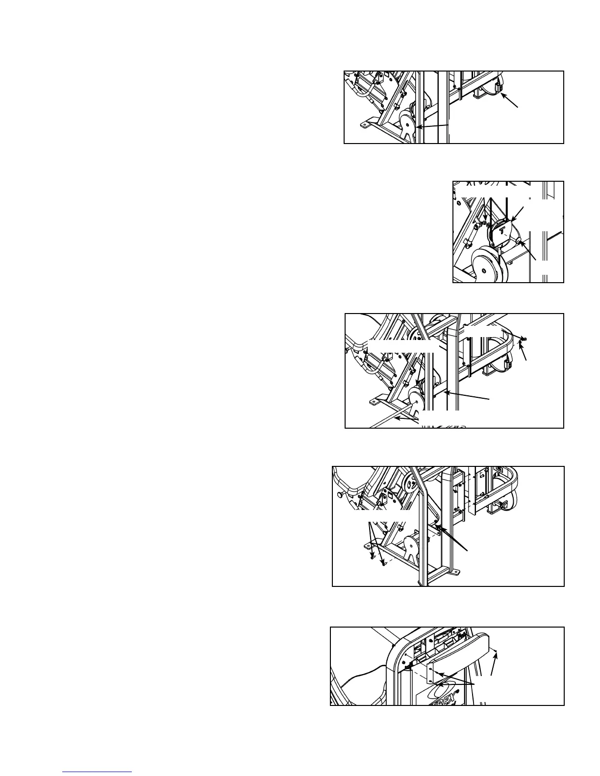
Rotate cam and disconnect weight stack belt from cam C.
(by loosening the two set screws on the belt clamp with
a 7/32” Allenwrench). See Figure 1.
Locate the pulley bracket that is located near the cam. D.
See Figure 2.
Remove bolt, washer and hex nut securing the pulley E.
to the pulley bracket.
Remove pulley from pulley bracket.F.
Remove one of the two BHSCS (Button Head Socket Cap Screws) G.
securing the pivot shaft. See Figure 3.
Carefully remove pivot shaft and pulley shaft. See Figure 3. H. NOTE: Be extremely
careful when removing shaft so you don’t ruin the threads on the shaft.
With an assistant, carefully remove the six BHSCS I.
securing the two halves of the frame. See Figure 4.
Carefully move each half through the door-way to the J.
desired location.
With an assistant, carefully attach each half together K.
using the six BHSCS removed in step 4I. See Figure 4.
Carefully attach pulley shaft using the pivot shaft and L.
BHSCS removed in steps 4G and 4H. See Figure 3.
Reconnect pulley/cable to pulley bracket (removed in M.
steps 4E and 4F).
Verify the two belts are routed properly (one belt from the N.
cam to the pulley bracket and the other belt connecting to
the arms).
Connect the weight stack belt to the belt clamp of O.
cam (removed in step 4C). See Figure 1.
Continue on, starting with Step 5B.P.
5. Install rubber feet and remove the back shrouds.
Carefully remove each (standard) cone-shaped A.
shipping support using a 3/4” socket or wrench.
Be sure machine is in desired location. B.
Carefully place rubber feet (supplied with machine) C.
on each foot of the frame.
Cut shipping tie securing top weight.D.
Lift top weight and turn the Increment Weight Adjusting E.
Knob to select all 15 lbs. (three increment weights each
side).
Remove the three Phillips head screws securing the top F.
(back) shroud and carefully remove the shroud. See
Figure 5.
Figure 2
Bolt
Pulley
Bracket
Hex Nut/Washer
Figure 3
BHSCS
Pivot Shaft
Washer
Pulley Shaft
Pulley/Cable
Figure 4
BHSCS (qty 6)
Nylon Locknut (6)
Figure 5
Phillips Head
Screw (3)
Figure 1
Set
Screws
Cam
 Loading...