Assembly
Page 4-3
Product Number 8800/8810 Owner’s Manual
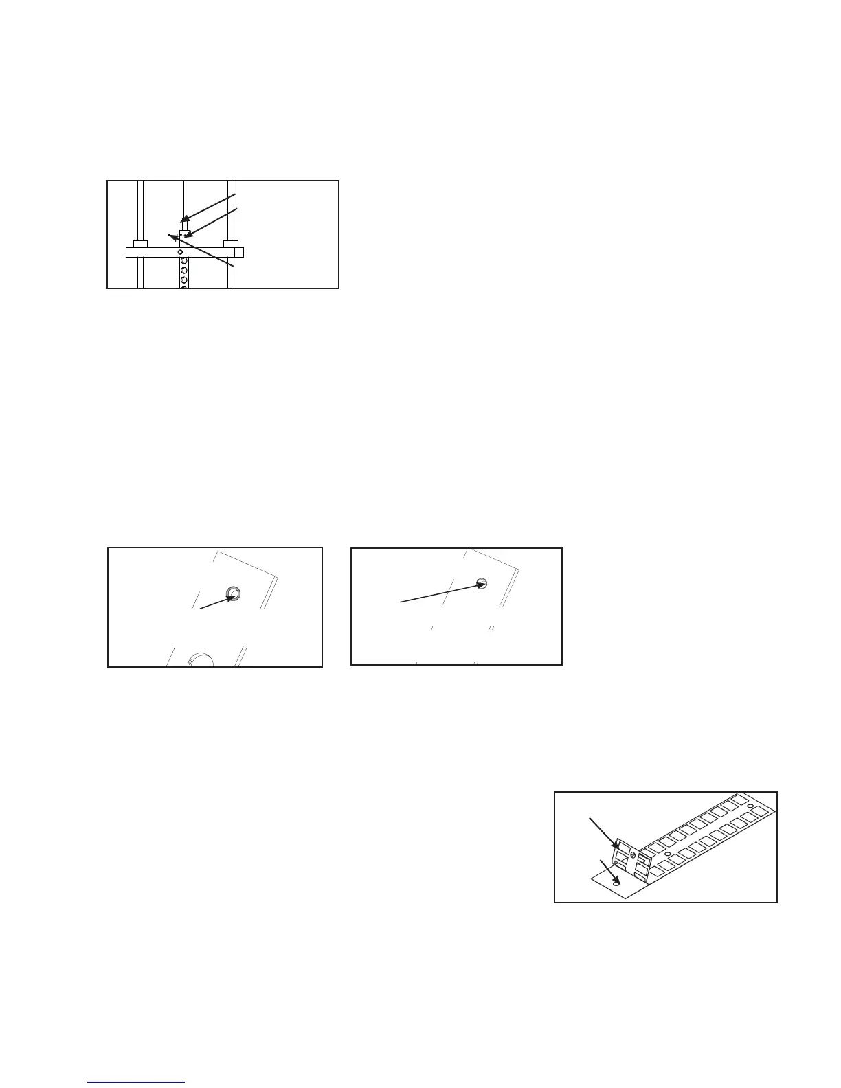
Figure 3
Repeat steps 6D - 6F for other guide rod.G.
Using a 3/16” pin punch and hammer, carefully remove roll pin securing cable end to top weight connec-H.
tor. See Figure 3.
Carefully lean guide rods slightly outward. I. NOTE: Excessive pressure on guide rods may
damage lower guide rod caps.
Slide top weight up and out of machine and carefully set aside.J.
Have an assistant hold guide rods vertical.K.
Carefully align weight plates over guide rods and slowly lower each weight plate. L.
NOTE: When installing weight plates, position plates so wide edges of bushings face upward and narrow
edges of bushings face downward. See Figures 4a and 4b.
Cable End
Top Weight
Connector
Roll Pin
NARROW bushing edge
WRONG
WIDE bushing
edge faces upward
CORRECT
NOTE: The narrow bushing
edge must face downward.
Figure 4a
Figure 4b
Repeat step 6L for each weight plate.M.
Carefully slide top weight (removed in step 6J) over guide rods.N.
7. Install weight plate decals.
NOTE: You have the option to use pounds, kilograms or both.
Slowly and carefully peel off back side of decal. See Figure 5. A.
NOTE: When peeling off back cover, make sure that the decals
remain attached to the front sticker.
Align holes in decal with appropriate holes in weight stack. B.
NOTE: Do not allow the adhesive to touch weight stack at this
time.
Figure 5
Front
Back
 Loading...