Product Number 8800/8810 Owner’s Manual
Assembly
Page 4-4
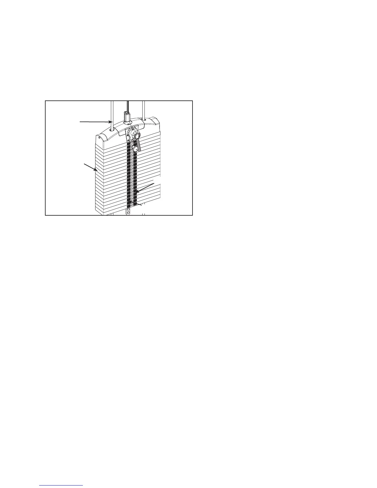
8. Cable routing.
Verify cable is routed through top of pulley bracket and then route cable end to top weight A.
connector.
Pull cable tight and secure in place with roll pin removed in step 6H.B.
Place weight stack pin in each plate to verify proper installation.C.
Without selecting any resistance, lift top weight up and down (simulating normal operation).D.
Have an assistant verify that the cable is moving smoothly and is routed straight from the pulley E.
bracket to the top of the weight plate connector.
9. Install back shrouds.
Carefully place shrouds into position.A.
Secure top cap in place with the two BHSCS removed in step 6A.B.
10. Separate Frame for 8800 (If needed to fi t thru doorway).
Remove shipping pallet (refer to step 4).A.
Locate insert plug. See Figure 7.B.
180
81.0
144.0
135.0
126.0
117.0
10
8.0
200
99.0
90.0
300
280
260
240
220
320
340
153.0
180.0
360
171.0
162.0
400
380
20
9.0
72.0
63.0
54.0
45.0
36.0
40
18.0
140
120
100
80
60
160
Figure 6
Weight
Stack
Guide
Rod
Pounds
Kilograms
Insert a guide pin through each hole of the template. C. NOTE: A guide pin can be anything that fi ts
through the weight stack hole, such as a weight stack selector pin.
Carefully align decal and rub it onto weight plates. D.
Carefully remove front side, leaving decals adhering to weight plates. See Figure 6.E.
 Loading...