ROBOT . HEAD to TOE
Product User’s Manual – MDDS10
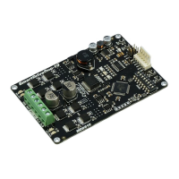
6. MOTOR CONNECTION
Similar to the power supply, connection to the motor can be made either via the terminal
block, or it can be soldered directly to the bottom layer pad.
For Mixed mode, especially for RC input mode (or Breakout board with Joystick soldered),
each terminal block must be connected to the same side of the motor. For example, left
terminal block connected to motor LEFT and right terminal block connected to motor
RIGHT. Then, user can test it by controlling the motor by using RC controller. If the motor
give wrong direction, reverse the polarity of the motor connection at the terminal block.
Created by Cytron Technologies Sdn. Bhd. – All Rights Reserved 10
 Loading...