EasyManua.ls Logo

DAE DEM720 User Manual

DAE DEM720
2 pages
To Next Page IconTo Next Page
Page #1 background imageLoading...
Page #1 background image

P1
1p2w,120V,50A,TA=10,60Hz

1p2w Energy Meter
Installation Guide
Front Panel
Terminals
Lead Seal
Dimensions
LCD Display
Communication
Indicators
Meter
Specifications
Shorting Plate
Serial Number
Reserved
Model Number
Meter Constant
Indicator
Connector Terminals
2012 S/N 30021716 DEM730
Weight: 495g (2.4lbs)
Unit: inches
Mounting
Wiring Diagram
LCD Display
* Must be tightly
screwed
Load
1.
2.
3.
4.
5.
Blinks twice
Firmware version
(actual version will vary)
Reserved
Reserved
Cumulative kWh




Display
Sequence
Description

1.
2.
3.
4.
Firmware version
Reserved
Reserved
Cumulative kWh



DisplaySequence Description

Power Up Display Sequence
●Normal Operating Display: Cumulative kWh
●Display On Button Tap
With one decimal place
1p2w,120V,50A,TA=10,60Hz
Tap button
2.30”
1.85”
0.24”
Screw Hole 0.2”
Screw Hole 0.2”
4.92”
0.40”
3.70”
0.24” 0.24”
Load
Circuit
Breaker
Power Source
AC110V or AC220V
L
N
Finished
0.47”
5.31”
4.17”
Power Cable: <High Voltage>
1.Please use wire size and type in accordance with
electrical regulations
2.Make sure that the wires are screwed tightly to
their terminals.
*Note: 14mm2 is the largest wire size that
can pass through the hole
**Note:
Select the model with the voltage (AC110V or
AC220V) appropriate for the required
application
Loop the copper
strand through
the hoop
Thread the copper
strand through the
lead seal
Crimp tight using
electrical pliers
Question and Answer IconNeed help?

Do you have a question about the DAE DEM720 and is the answer not in the manual?

DAE DEM720 Specifications

General IconGeneral
BrandDAE
ModelDEM720
CategoryMeasuring Instruments
LanguageEnglish

Summary

Front Panel Components

Model Number and Indicators

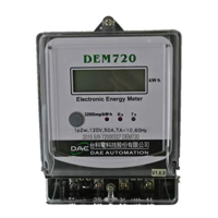
Details the energy meter's model number, constant indicator, and communication indicators.

Serial Number and Specifications

Provides information on the serial number, reserved fields, and meter specifications.

Dimensions and Mounting

Physical Dimensions

Specifies the physical measurements and unit weight of the energy meter.

Mounting Holes

Details the size and placement of mounting holes for installation.

Terminal Connections

Power Cable Requirements

Guidance on power cable type, wire size, and secure terminal connection.

Wire Size Limit

Note on the maximum wire size (14mm2) that can fit through the terminal hole.

Wiring Diagram and Voltage Selection

Circuit Diagram

Illustrates the wiring connections for AC110V or AC220V power sources.

Voltage Appropriateness

Instruction to select the correct voltage model for the application.

Lead Seal Procedure

Applying the Lead Seal

Steps for looping the copper strand and crimping the lead seal.

LCD Display Information

Power Up Display Sequence

Details the display sequence shown when the meter powers on.

Normal Operating Display

Indicates cumulative kWh displayed during normal operation.

Button Tap Display

Describes the display change when the button is tapped.

Installation Checklist

Before Powering On Checks

Ensures secure mounting and correct wiring before energizing the meter.

After Powering On Checks

Verifies proper LCD display and load indicator blinking.

Safety Warnings and Precautions

Danger: Electric Shock Hazard

Warning to turn off power to prevent electric shock during installation.

General Installation Warnings

Advice on qualified personnel, electrical rules, and environmental hazards.

Related product manuals