This document serves as a service manual for the Daewoo Mini Component System, covering models AMI-716L/716R, AMI-816L/816R, and AMI-816LS/816LSR. It provides comprehensive instructions for adjustments, exploded views, wiring diagrams, block diagrams, schematic diagrams, PCB pattern layouts, and electrical parts lists, intended for qualified service personnel.
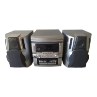
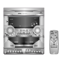
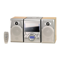
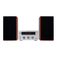
The Mini Component System is designed to provide a versatile audio experience, integrating multiple functions into a single unit. Its primary function is to serve as a complete audio system, encompassing radio reception, compact disc playback, and cassette tape recording and playback.
Function Description
The system integrates several key functional blocks to deliver its audio capabilities:
- Tuner Section: This section handles radio frequency (RF) reception for both FM and AM bands. It includes an FM RF module, an IF+MPX (Intermediate Frequency and Multiplex) unit, an AM RF+OSC (Oscillator) unit, and a PLL (Phase-Locked Loop) for stable tuning. An optional RDS (Radio Data System) feature is also supported, allowing for the display of additional broadcast information.
- CD Section: Dedicated to compact disc playback, this section comprises a CD mechanism, an ASSP (Application Specific Standard Product) for controlling sled, spindle, tracking, focusing, and roulette movements, a DSP (Digital Signal Processor) for audio processing, and an LPF (Low-Pass Filter). The CD mechanism is designed for reliable disc handling and data retrieval.
- Tape Section: This part of the system facilitates both recording and playback of cassette tapes. It features a tape mechanism, an R/P SW (Record/Playback Switch) for mode selection, and a PLAY/REC EQ (Equalizer) to optimize audio quality for both functions. A REC OSC (Record Oscillator) is included for bias generation during recording.
- Power/Amplifier Section: This is the core audio output stage, responsible for amplifying the audio signals from all sources. It includes a POWER AMP IC, a REGULATOR for managing various voltage supplies (+12V UN/SW, +5.6V UN/SW, +8.6V SW, +12V SW), and connections for headphones and speakers. A POWER TRANS (Transformer) supplies the necessary power to the system.
- Control Section: The central intelligence of the system is managed by a U-COM (Microcontroller Unit) and a KEY CONTROL interface. This section processes user inputs, controls the various functional blocks, and manages the overall operation of the system. An EQ DISPLAY (Equalizer Display) provides visual feedback for audio settings, and an EEPROM (Electrically Erasable Programmable Read-Only Memory) stores system settings and user preferences. A VFD (Vacuum Fluorescent Display) provides visual information to the user.
- Function Pre-Amp and DSP: An integrated FUNCTION PRE AMP processes audio signals before they reach the main amplifier, allowing for adjustments like PRESET EQ (Equalizer) and volume control (VR). A DSP (Digital Signal Processor) further enhances audio quality, with an optional configuration for specific models. An AUX input is also available for connecting external audio sources.
Usage Features
The Mini Component System is designed for user convenience and safety.
- Ventilation: Proper ventilation is crucial for the appliance's longevity. It should be placed in a location that does not obstruct airflow, avoiding surfaces like beds, sofas, or rugs, and not in enclosed spaces like bookcases or cabinets without adequate air circulation.
- Heat Management: The system should be kept away from heat sources such as radiators, heat registers, stoves, or other heat-producing appliances to prevent overheating.
- Power Supply: It must be connected to a power supply of the type specified in the operating instructions or marked on the appliance.
- Grounding and Polarization: Precautions are in place to ensure proper grounding and polarization, which are essential for electrical safety.
- Power Cord Protection: The power-supply cord should be routed to prevent it from being walked on or pinched by other items, paying particular attention to the plug, convenience receptacles, and the point where it exits the appliance.
- Protective Attachment Plug: The appliance is equipped with an attachment plug that includes overload protection, a key safety feature. Instructions for replacement or resetting of this protective device are provided.
- Cleaning: The appliance should only be cleaned as recommended by the manufacturer to avoid damage.
- Outdoor Antenna Grounding: If an outdoor antenna is connected, it must be properly grounded to protect against voltage surges and static charges, following the guidelines of the National Electrical Code.
Maintenance Features
The service manual outlines specific procedures for maintaining and troubleshooting the system, primarily intended for qualified service personnel.
- Adjustments: Detailed instructions are provided for tuner alignment (FM RF, IF, and Auto Stop Sensitivity) and CD section adjustments (RF Level Check and E-F Balance Adjustment). These involve using specialized equipment like signal generators, oscilloscopes, and VTVMs to ensure optimal performance.
- Tape Alignment: The manual includes procedures for tape speed adjustment, azimuth adjustment, and recording bias oscillator frequency adjustment. These adjustments are critical for maintaining high-quality tape playback and recording.
- Exploded Views and Parts Lists: Comprehensive exploded views and mechanical parts lists are provided, allowing service personnel to identify and replace specific components easily.
- Wiring and Schematic Diagrams: Detailed wiring diagrams and schematic diagrams are included for all major functional blocks (Power/Amp, CD, Tuner, Tape, Control). These diagrams are essential for understanding the internal connections and circuit operations, aiding in troubleshooting and repair.
- PCB Pattern Layouts: PCB pattern layouts are provided for the Power/Amp/Tuner/Tape, CD, and Control boards. These layouts help service personnel locate components on the circuit boards for inspection and repair.
- Electrical Parts List: A complete list of electrical parts, including their codes, descriptions, quantities, and locations, is provided for each model. This list is invaluable for ordering replacement parts and ensuring compatibility.
- Non-use Periods: For extended periods of non-use, the power cord should be unplugged from the outlet to prevent potential hazards.
- Object and Liquid Entry: Care must be taken to prevent objects from falling into or liquids from spilling into the enclosure, as this can cause damage.
- Damage Requiring Service: The manual specifies conditions that necessitate professional service, such as a damaged power-supply cord or plug, foreign objects or liquids inside the appliance, exposure to rain, abnormal operation, or physical damage to the enclosure.
- Servicing: Users are explicitly advised not to attempt servicing beyond what is described in the operating instructions. All other servicing should be referred to qualified service personnel to ensure safety and proper repair.