Do you have a question about the Daewoo XG-332V and is the answer not in the manual?
Procedures for FM/AM tuner alignment and calibration.
Procedures for tape speed, azimuth, and bias oscillator adjustments.
Electrical schematics for the main and power supply circuits.
Electrical schematics for the main control and signal processing circuits.
Electrical schematics for the FM/AM tuner and signal reception.
Electrical schematics for the tape deck mechanism and audio circuits.
Electrical schematics for the front panel controls and display.
Electrical schematics for the MP3 and VCD playback circuits.
Electrical schematics for the karaoke function and microphone input.
Electrical schematics for the power supply and voltage regulation.
Top-side PCB layout for the main board components.
Bottom-side PCB layout for the main board components.
PCB layout for the front panel interface and controls.
PCB layout for the MP3 and VCD playback module.
PCB layout for the karaoke function module.
PCB layout for the power supply circuit in CE regions.
PCB layout for the power supply circuit in other regions.
PCB layout for the power supply circuit in CE regions.
PCB layout for the power supply circuit in other regions.
| Brand | Daewoo |
|---|---|
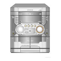
| Model | XG-332V |
| Category | Stereo System |
| Language | English |