Do you have a question about the Daewoo AMI-225M and is the answer not in the manual?
Essential operational guidelines and precautions against electrical hazards.
Specific warnings for laser use and general maintenance cautions.
Procedures for antenna grounding and when to seek professional service.
Procedures for aligning the FM tuner section for optimal reception.
Steps for checking and adjusting the CD player's RF signal and balance.
Procedures for tape speed, azimuth, and bias oscillator frequency adjustments.
Visual representation and listing of all mechanical components used in the appliance.
Diagram illustrating the electrical connections between different modules and components.
High-level representation of the system's functional blocks and data flow.
Detailed circuit schematic for the power supply and audio amplification stages.
Detailed circuit schematic for the CD playback mechanism and control.
Detailed circuit schematic for the FM/AM tuner and PLL components.
Detailed circuit schematic for the tape playback and recording functions.
Detailed circuit schematic for the main control unit and user interface.
Printed circuit board layout for the power, amplifier, and tuner sections.
Printed circuit board layout for the CD player section.
Printed circuit board layout for the front panel controls and display.
Comprehensive list of electronic components used in the appliance with part numbers.
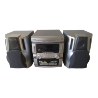
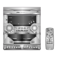
This document serves as a comprehensive service manual for the DAEWOO MINI COMPONENT SYSTEM, specifically covering models AMI-225M/MU and AMI-325M/MU. It provides essential information for the proper operation, adjustment, and maintenance of the device, ensuring both user safety and optimal performance.
The DAEWOO MINI COMPONENT SYSTEM is an integrated audio device designed to provide a versatile listening experience. It incorporates multiple audio sources, including a Tuner for radio reception, a CD player for digital audio disc playback, and a Tape deck for cassette playback and recording. The system features a Power/Amplifier section responsible for amplifying audio signals to drive speakers and a Control section that manages user input and system functions.
The Tuner section is equipped to receive FM and AM radio broadcasts. It includes an IF+MPX (Intermediate Frequency + Multiplex) unit for processing FM signals, an AM RF+OSC (Radio Frequency + Oscillator) unit for AM reception, and a PLL (Phase-Locked Loop) circuit for stable tuning. The system supports both manual and auto-stop sensitivity adjustments for precise station tuning.
The CD section is designed for playing compact discs. It comprises a CD deck mechanism, an ASSP (Application Specific Standard Product) for signal processing, a DSP (Digital Signal Processor) for audio enhancement, and a Motor Driver to control the sled, spindle, tracking, focusing, and roulette mechanisms. This intricate setup ensures accurate data retrieval and high-quality digital audio output.
The Tape section facilitates the playback and recording of audio cassettes. It includes a R/P SW (Record/Playback Switch) to toggle between modes, a Play/Rec EQ (Equalizer) to optimize audio characteristics for playback and recording, and a REC OSC (Record Oscillator) for bias signal generation during recording. The tape mechanism is designed for reliable cassette handling.
The Power/Amplifier section is the core of the system's audio output. It includes a Power Amp responsible for amplifying the audio signals from the various sources to a level suitable for driving speakers. A Regulator circuit ensures stable power supply to all internal components, while a Power Transformer converts the incoming AC power to the necessary voltages. The system also features a Headphone output for private listening.
The Control section, managed by a U-COM (Microcontroller Unit), acts as the central processing unit for the entire system. It interprets user commands from the front panel, manages the operational states of the Tuner, CD, and Tape sections, and controls the LED Display for visual feedback. An EEP ROM (Electrically Erasable Programmable Read-Only Memory) stores system settings and user preferences.
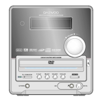
The DAEWOO MINI COMPONENT SYSTEM is designed for straightforward operation, offering a range of features to enhance the user experience. The front panel provides intuitive controls for selecting audio sources (Tuner, CD, Tape, AUX), adjusting volume, and managing playback functions. The LED Display provides clear visual feedback on the current operating mode, radio frequency, track number, and other relevant information.
For radio listening, the Tuner section allows users to manually tune to desired frequencies or utilize auto-stop sensitivity for automatic station searching. The system's PLL circuit ensures stable reception, minimizing drift and maintaining clear audio.
The CD player supports standard audio CDs, providing high-fidelity digital audio playback. Users can control playback functions such as play, pause, stop, skip track, and fast forward/rewind. The DSP enhances the audio quality, delivering a rich and clear sound.
The Tape deck offers both playback and recording capabilities. Users can enjoy their cassette collection or record audio from the radio or CD player onto a blank cassette. The Play/Rec EQ optimizes the audio for both functions, ensuring good sound quality.
An AUX (Auxiliary) input allows users to connect external audio devices, expanding the system's versatility. This enables playback from smartphones, MP3 players, or other audio sources through the component system's amplifier and speakers.
The system incorporates a PRESET EQ + VR (Volume Control) for audio customization, allowing users to adjust sound characteristics to their preference. The Headphone output provides a convenient option for personal listening without disturbing others.
The service manual emphasizes several key aspects for maintaining the DAEWOO MINI COMPONENT SYSTEM, focusing on safety, performance, and longevity.
Safety Precautions: The manual begins with critical safety warnings, including instructions to prevent fire and electric shock. It advises against exposing the appliance to rain or moisture and warns against removing covers due to the risk of electric shock. Servicing should only be performed by qualified personnel. Specific warnings regarding laser safety for the CD unit are provided, highlighting the potential for eye injury if covers are removed by unauthorized individuals. It also includes instructions for proper grounding of outdoor antennas and precautions for power cords and attachment plugs to prevent hazards.
Adjustments: The manual details specific adjustment procedures for optimal performance of the Tuner and Tape sections.
Exploded View and Parts List: The manual includes detailed exploded views and comprehensive parts lists for the mechanical components. This information is invaluable for identifying and ordering replacement parts during repairs, ensuring that only specified components are used.
Wiring Diagram and Schematic Diagram: Detailed wiring diagrams illustrate the interconnections between different PCB assemblies and components, such as the main PCB, front PCB, CD mechanism, and power transformer. Schematic diagrams for the Power/Amp, CD, Tuner, Tape, and Control sections provide circuit-level details, essential for troubleshooting and component-level repairs.
PCB Pattern Layout: PCB pattern layouts are provided for the Power/Amp/Tuner, CD, and Front PCBs. These layouts show the placement of components and traces, aiding technicians in locating specific parts and understanding circuit flow during diagnosis and repair.
Electrical Parts List: A comprehensive electrical parts list is included, detailing all electrical components by part name, code, and description. This list is crucial for identifying correct replacement parts, ensuring compatibility and maintaining the system's original performance and safety standards.
The overall design of the manual ensures that technicians and service personnel have all the necessary information to safely and effectively diagnose, repair, and maintain the DAEWOO MINI COMPONENT SYSTEM, thereby extending its operational life and ensuring continued user satisfaction.
| Type | Mini Hi-Fi System |
|---|---|
| Tuner Bands | FM/AM |
| CD Player | Yes |
| Tape Player | Yes |
| Radio | Yes |
| Equalizer | 5-Band |
| Output Power | 25W x 2 (RMS) |
| Cassette Deck | Dual |
| Speakers | 2-way speakers |