EasyManua.ls Logo

Daewoo DVR-1181D User Manual

Daewoo DVR-1181D
43 pages
To Next Page IconTo Next Page
Page #1 background imageLoading...
Page #1 background image
Service Manual
Model : DVR-1989D
DVR-1989D(KD)
DVR-1989D(BB)
DVR-1989D(GB)
DVR-1983D
DVR-1983D(KD)
DVR-1983D(BB)
DVR-1983D(GB)
DVR-1181D
DVR-1181D(KD)
DVR-1181D(BB)
DVR-1181D(GB)
DAEWOO ELECTRONICS CO., LTD.
All manuals and user guides at all-guides.com
all-guides.com
Question and Answer IconNeed help?

Do you have a question about the Daewoo DVR-1181D and is the answer not in the manual?

Daewoo DVR-1181D Specifications

General IconGeneral
BrandDaewoo
ModelDVR-1181D
CategoryVCR
LanguageEnglish

Summary

Safety Check after Servicing

1. Insulation resistance test

Checks insulation integrity between power cord and exposed parts.

2. Dielectric strength test

Verifies dielectric strength between power cord and exposed parts.

3. Clearance distance

Measures critical clearance distances between components and metal parts.

4. Leakage current test

Measures current leakage from exposed parts to ground.

SECTION 1. GENERAL

1.1 IDENTIFICATION AND OPERATION OF CONTROLS

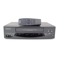
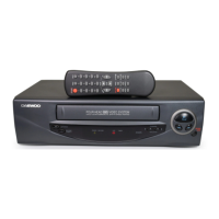
Describes front panel controls, buttons, and indicators.

External Connections and Ports

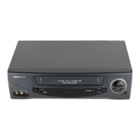
Details all input/output terminals and connectors on the unit.

SECTION 2. ELECTRICAL ADJUSTMENTS

2-1. ALIGNMENT AND ELECTRICAL ADJUSTMENT

General overview of adjustments using test tapes and signals.

2-2. SERVO-LOGIC CIRCUIT ADJUSTMENT METHOD

Procedure for adjusting servo and logic circuits.

2-3. VIDEO CIRCUIT ADJUSTMENT METHOD

Procedures for various video circuit adjustments.

2-4. AUDIO CIRCUIT ADJUSTMENT METHOD

Methods for adjusting audio playback and recording levels.

SECTION 3. CIRCUIT DIAGRAM

3-1. CONNECTION DIAGRAM

Shows how different parts of the circuit are interconnected.

3-2. POWER CIRCUIT

Detailed schematic of the power supply section.

3-3. SERVO/SYSCON CIRCUIT

Schematic of the servo and system control circuits.

3-4. VIDEO CIRCUIT

Schematic of the video processing and output circuits.

3-5. PRE-AMP CIRCUIT

Schematic of the pre-amplifier section.

3-6. AUDIO CIRCUIT

Schematic of the audio processing and output circuits.

3-7. LOGIC SW CIRCUIT (DVR-1181 SERIES)

Circuit diagram for the logic switching circuit of the DVR-1181 series.

3-8. LOGIC SW CIRCUIT (DVR-1383 SERIES)

Circuit diagram for the logic switching circuit of the DVR-1383 series.

3-9. LOGIC SW CIRCUIT (DVR-1989 SERIES)

Circuit diagram for the logic switching circuit of the DVR-1989 series.

SECTION 4. EXPLODED VIEWS AND PARTS LIST

4-1. PACKING ASSEMBLY

Lists parts included in the product packaging.

4-2. SET ASSEMBLY

Lists major components of the main unit assembly.

4-3. PANEL FRONT ASSEMBLY (DVR-1181 SERIES)

Lists parts for the front panel of the DVR-1181 series.

4-4. PANEL FRONT ASSEMBLY (DVR-1383 SERIES)

Lists parts for the front panel of the DVR-1383 series.

4-5. PANEL FRONT ASSEMBLY (DVR-1989 SERIES)

Lists parts for the front panel of the DVR-1989 series.

4-6. MAIN CHASSIS ASSEMBLY

Lists components for the main chassis assembly.

SECTION 5. COMPONENTS LOCATION GIDE ON PCB

5-1. PCB MAIN AS

Identifies locations of components on the main PCB.

5-2. PCB FRONT AS

Identifies locations of components on the front PCB for different series.

5-3. PCB POWER ASSEMBLY

Identifies locations of components on the power PCB.

SECTION 6. ELECTRICAL PARTS LIST

6-1. STANDARD PART NUMBER CODING

Explains the coding system for standard electronic parts.

6-2. ELECTRICAL PART LIST BY ASSEMBLIES

Lists electrical parts categorized by assembly.

Related product manuals