Do you have a question about the Daewoo DVR-1989D and is the answer not in the manual?
Tests the insulation resistance of the set to ensure safety compliance.
Verifies the dielectric strength between power cord prongs and exposed parts.
Confirms specified clearance distances between components and surrounding parts.
Measures leakage current between earth ground and accessible parts.
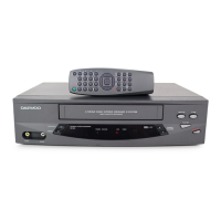
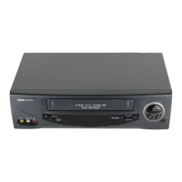
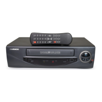
Identifies and explains the operation of all controls on the VCR unit.
Procedure for aligning and making electrical adjustments using test tapes and video signals.
Method for adjusting the servo-logic circuit, focusing on video head switching position.
Procedures for adjusting video circuit levels, Y-signal output, and sync tip frequency.
Methods for adjusting audio playback levels, frequency response, and bias current.
Diagram illustrating the overall connections between different parts of the VCR.
Schematic diagram of the VCR's power supply circuit.
Circuit diagram for the servo control and system controller.
Circuit diagram detailing the video processing section of the VCR.
Schematic of the pre-amplifier circuit for signal boosting.
Circuit diagram for the audio processing and playback section.
Logic switch circuit diagram specific to the DVR-1181 series.
Logic switch circuit diagram specific to the DVR-1383 series.
Logic switch circuit diagram specific to the DVR-1989 series.
List of parts and components included in the product's packaging.
Exploded view and parts list for the main chassis and overall set assembly.
Detailed parts list for the front panel assembly of the DVR-1181 series.
Detailed parts list for the front panel assembly of the DVR-1383 series.
Detailed parts list for the front panel assembly of the DVR-1989 series.
Comprehensive parts list for the main chassis of the device.
Component location guide for the main PCB, listing test points and variable resistors.
Component location guide for the front PCB assemblies.
Component location guide for the power supply PCB.
Explains coding for resistors, capacitors, and fuses.
Lists electrical parts categorized by assembly.
List of power PCB components and their specifications.
List of pre-amplifier PCB components and their specifications.
List of front PCB components for DVR-1181 series.
List of front PCB components for DVR-1383 series.
| Type | VCR |
|---|---|
| Brand | Daewoo |
| Model | DVR-1989D |
| Playback Formats | VHS |
| Recording Formats | VHS |
| Tuner | NTSC |
| Remote Control | Yes |
| Power Consumption | 20W |
| Inputs | Composite |
| Outputs | Composite |