6
2-2. SERVO-LOGIC CIRCUIT ADJUSTMENT METHOD
1. VIDEO HEAD SWITCHING POSITION
1) Play back the test tape.
2) Set the oscilloscope in the CHOP mode connect the CH1 to SW pulse PT01 2 PIN the CH2 to TP396 with CH1 triggering.
3) Adjust RV501 for the positive trigger until 6.5H¡ 0.5H cycles before the vertical SYNC pulse.
2-3. VIDEO CIRCUIT ADJUSTMENT METHOD
1. E E VIDEO LEVEL
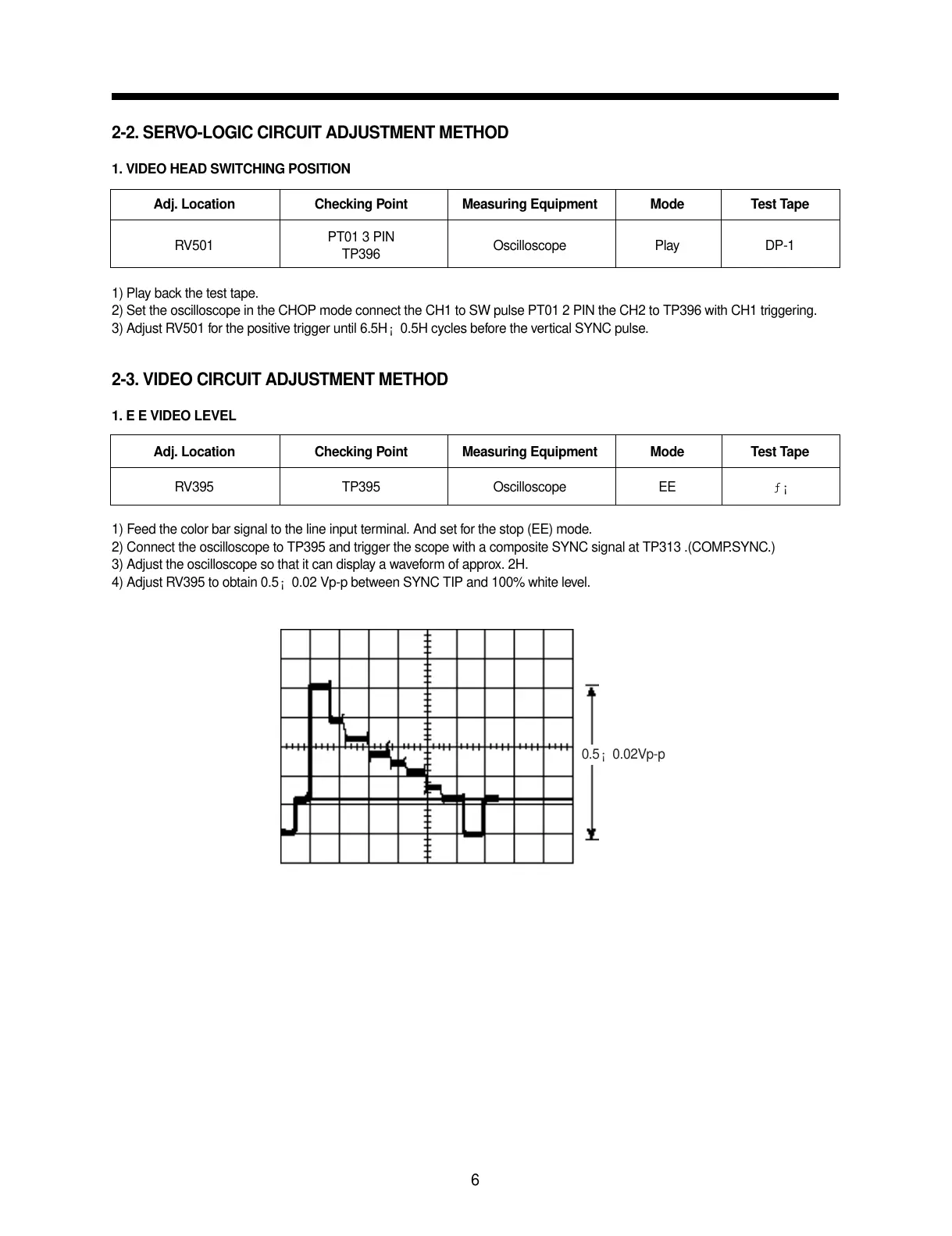
1) Feed the color bar signal to the line input terminal. And set for the stop (EE) mode.
2) Connect the oscilloscope to TP395 and trigger the scope with a composite SYNC signal at TP313 .(COMP.SYNC.)
3) Adjust the oscilloscope so that it can display a waveform of approx. 2H.
4) Adjust RV395 to obtain 0.5¡ 0.02 Vp-p between SYNC TIP and 100% white level.
Adj. Location Checking Point Measuring Equipment Mode Test Tape
RV501
PT01 3 PIN
Oscilloscope Play DP-1
TP396
Adj. Location Checking Point Measuring Equipment Mode Test Tape
RV395 TP395 Oscilloscope EE ƒ¡
0.5¡ 0.02Vp-p