2. PLAYBACK Y-SINGAL OUTPUT LEVEL
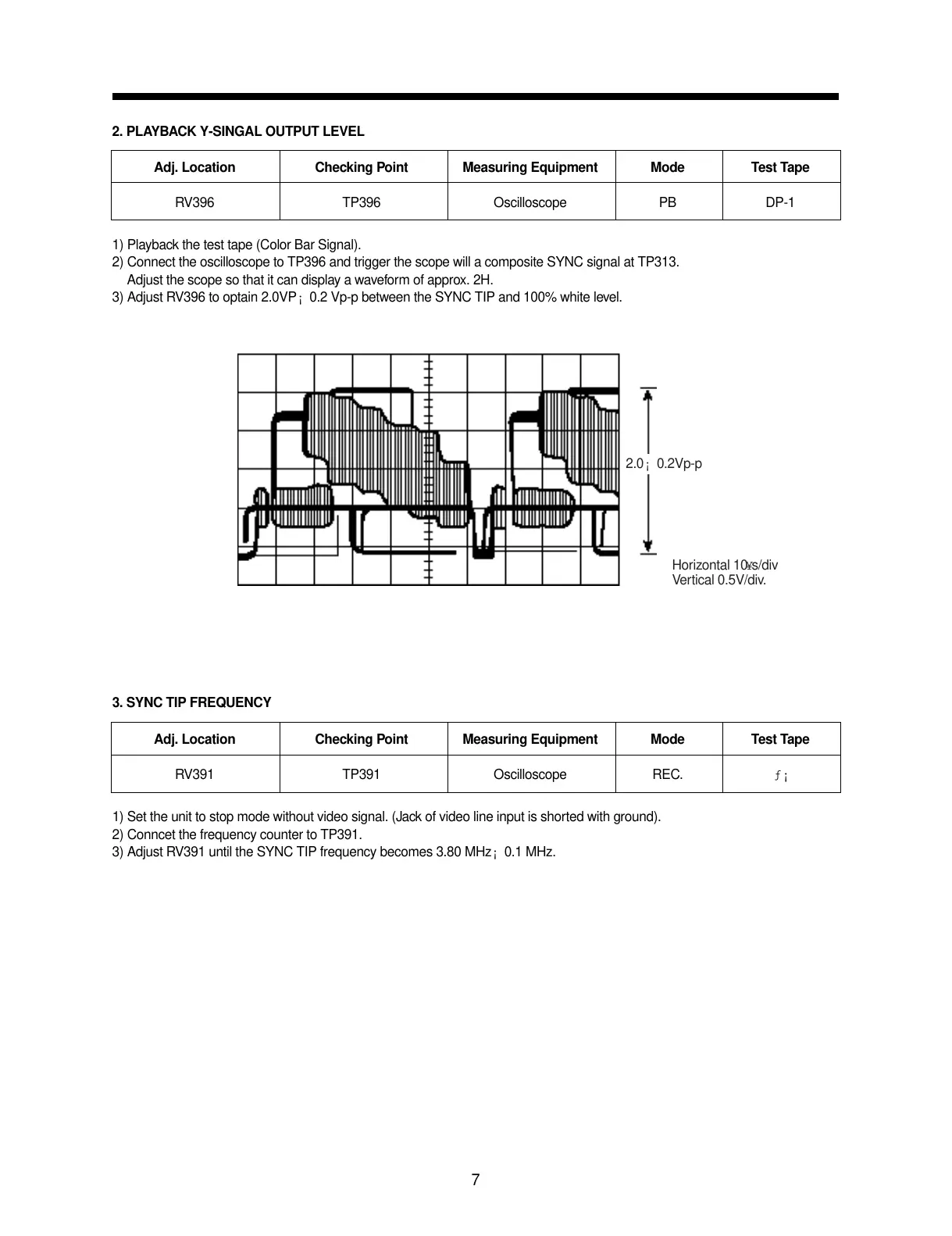
1) Playback the test tape (Color Bar Signal).
2) Connect the oscilloscope to TP396 and trigger the scope will a composite SYNC signal at TP313.
1) Adjust the scope so that it can display a waveform of approx. 2H.
3) Adjust RV396 to optain 2.0VP¡ 0.2 Vp-p between the SYNC TIP and 100% white level.
3. SYNC TIP FREQUENCY
1) Set the unit to stop mode without video signal. (Jack of video line input is shorted with ground).
2) Conncet the frequency counter to TP391.
3) Adjust RV391 until the SYNC TIP frequency becomes 3.80 MHz¡ 0.1 MHz.
7
Adj. Location Checking Point Measuring Equipment Mode Test Tape
RV396 TP396 Oscilloscope PB DP-1
Adj. Location Checking Point Measuring Equipment Mode Test Tape
RV391 TP391 Oscilloscope REC. ƒ¡
2.0¡ 0.2Vp-p
Horizontal 10¥s/div
Vertical 0.5V/div.