5
For these adjustment, use the equipment mentioned below
and proceed by using the alignment tape and video signal.
Instrument and Tools Required
1. Color TV receiver.
2. Oscilloscope having 10 MHz or more bandwidth.
3. Color-bar generator.
4. Frequency counter.
5. VTVM.
6. VOM (20 Kµ/V).
7. Audio oscillator.
8. Audio attenuator.
Signal Level and Input and Output Impedance
Requirement
1. Video input: Negative sync., 1Vp-p standard composite
1. video signal, 75Ω.
2. Video output: Same as above.
3. Audio input: Line - 10dBs, 47KΩ.
4. Audio output: -5dBs, 10KΩ or less.
Adjustment Sequence
The VCR should be adjusted in the sequence shown below.
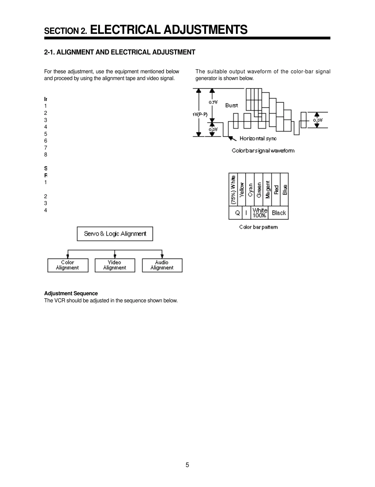
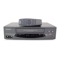
The suitable output waveform of the color-bar signal
generator is shown below.
SECTION 2.
ELECTRICAL ADJUSTMENTS
2-1. ALIGNMENT AND ELECTRICAL ADJUSTMENT