Do you have a question about the Daewoo FR-4501K and is the answer not in the manual?
Safety guidelines and precautions for servicing the microwave.
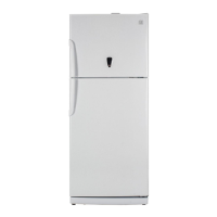
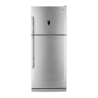
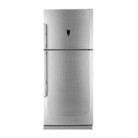
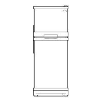
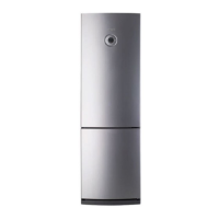
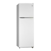
Provides external dimensions for refrigerator models.
Identifies external parts of the refrigerator with numbered labels.
Details the outline specifications of the refrigerator models.
Lists and describes various electric components and their part codes.
Provides specifications for the refrigerator thermostat.
Lists specifications for the defrost timer.
Information on urethan freezer door assembly.
Information on urethan refrigerator door assembly.
Describes the function of the temperature control button.
Explains the operation and features of the quick mode.
Explains the determination and conditions for defrosting periods.
Describes the normal and forced defrosting modes and procedures.
Illustrates the electrical wiring connections for various models.
Shows the detailed circuit diagram of the refrigerator's electronic system.
Illustrates the air circulation paths within the refrigerator.
Depicts the refrigerant flow cycle within the refrigerator system.
Step-by-step guide to remove the front cover lamp.
Instructions for removing the louver F component.
Guide to detach the right control box cover.
Instructions for removing the front control panel.
Provides a comprehensive exploded view of the refrigerator components.
Comprehensive list of all parts with their codes and descriptions.
| Brand | Daewoo |
|---|---|
| Model | FR-4501K |
| Category | Refrigerator |
| Language | English |