G420E/G424E Tier LP Engine Test And Adjustments 76
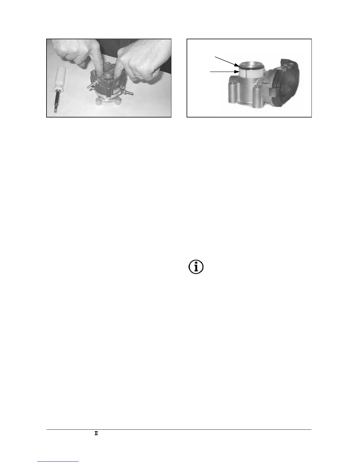
3. Check for free travel of the mixer’s piston
diaphragm assembly by pushing the piston
diaphragm downward (Figure M18). If you detect
any binding, loosen the retaining screws, re-align
the gasket and re-tighten the retaining screws.
Check for binding again, if the piston assembly
moves freely, re-torque the fasteners and continue.
4. Install the manifold adapter by placing the
manifold gasket between the manifold and the
manifold adapter. The manifold adapter should be
mounted with the TMAP sensor ports facing the
thermostat housing. Tighten the two internal
socket bolts to specified torque values.
5. Place the throttle bottom gasket between the
electronic throttle assembly and the manifold
adapter. Place the throttle assembly on top of the
gasket aligning the four mounting holes with the
threaded holes in the manifold adapter. The
plastic motor assembly cover, of the electronic
throttle assembly should be facing opposite of the
TMAP sensor mounting holes.
6. Place the O-ring Spacer over the outside throat of
the throttle. This spacer is necessary to assure
that the O-ring, which seals the throttle to the
adapter, properly seats against the throttle adapter.
7. Place the throttle adapter O-ring over the outside
throat of the throttle, below the throttle bore
retaining lip and on top of the O-ring Spacer
(Figure M19). Apply a generous amount of
lubricating grease (vacuum grease) to the O-ring
and fully seat it against the machined surface.
8. Carefully slide the pre-assembled mixer/throttle
adapter assembly over the throat of the throttle
using a rocking motion, aligning the mounting
holes of the adapter with the mounting holes of
the throttle Face the fuel inlet of the mixer toward
the plastic motor assembly cover of the electronic
throttle assembly.
NOTE
Avoid pinching the O-ring in the cutaway
of the throttle adapter. This will damage
the O-ring and cause a manifold leak in
the system.
O-Ring
Spacer
Figure M18 Figure M19