24
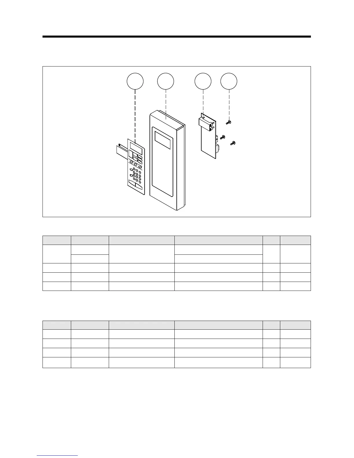
(1) Remove the screw which secure the control panel, push up two snap fits and draw forward the control panel assembly.
(2) Remove four screws which secure the PCB assembly to control panel.
(3) Disconnect membrane tail from the connector of the PCB assembly.
(4) Detach membrane from the control panel.
(5) Reverse the above steps for reassembly.
REF NO. PART CODE PART NAME DESCRIPTION Q’TY REMARK
B01
3518522130
SWITCH MEMBRANE
KOR-1A4G0A
1
3518522140 KOR-1A4H0A/1A
B02 3516722320 CONTROL-PANEL ABS AF-315/345 HFA-700HT 1
B03 PKMPMSXN00 PCB AS KOR-1A1G0A 1
B04 7122401211 SCREW TAPPING T2S TRS 4* 12 MFZN 3
2) KOR-1A4G(H)
REF NO. PART CODE PART NAME DESCRIPTION Q’TY REMARK
B01 3518523770 SWITCH MEMBRANE KOR-1A7G9A27 1
B02 3516722380 CONTROL-PANEL ABS AF-348 VT-0826 1
B03 PKMPMSXN00 PCB AS KOR-1A1G0A 1
B04 7122401211 SCREW TAPPING T2S TRS 4*12 MFZN 4
3)KOR-1A7G