H
hendersonchristinaAug 18, 2025
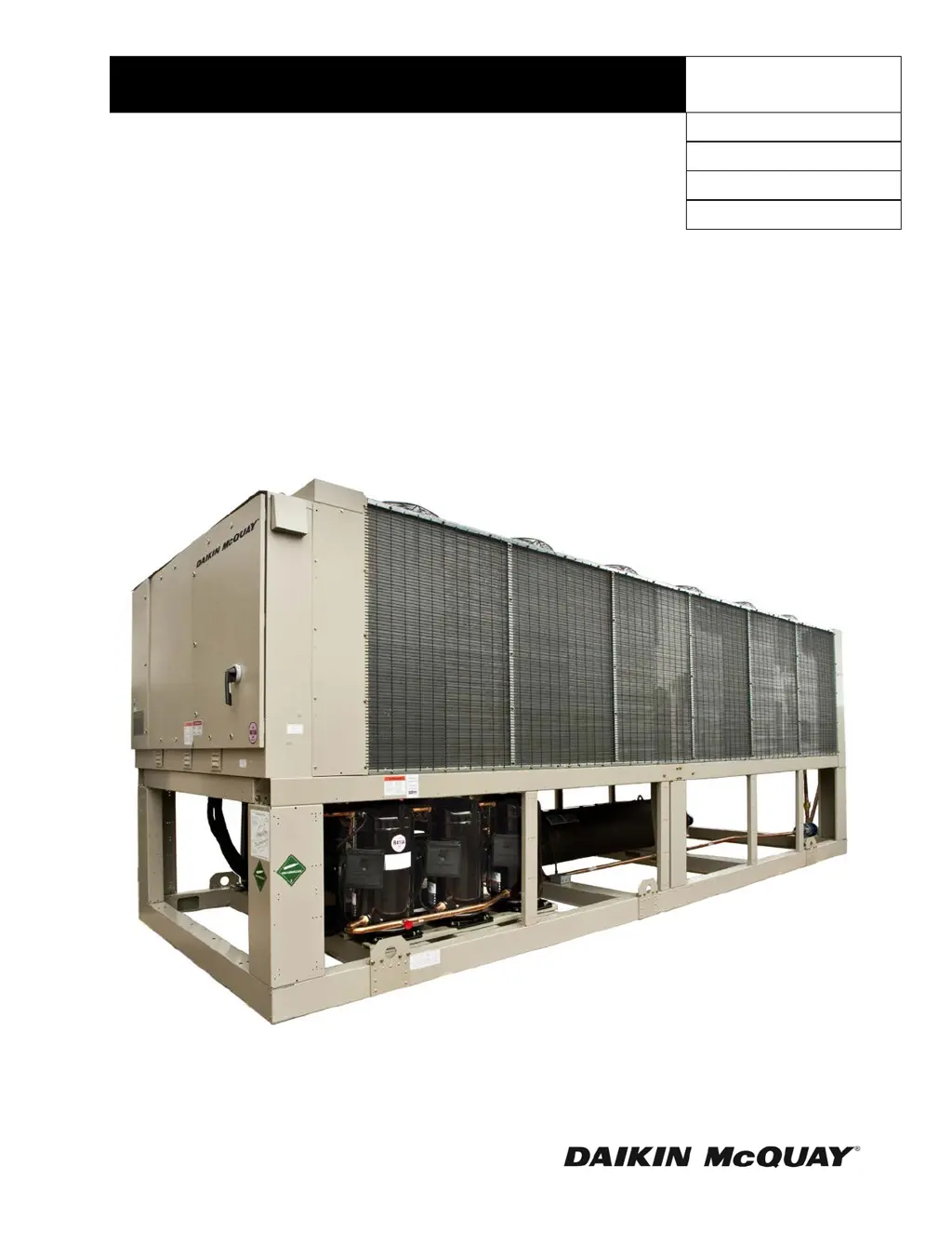
How to troubleshoot Daikin McQuay AGZ-D 25 Chiller compressor that will not run?
- RRose GregoryAug 18, 2025
If the compressor of your Daikin McQuay Chiller isn't running, start by checking the main switch to ensure it's closed. Then, inspect the electrical circuits and motor windings for any shorts or grounds, and look for potential overloading. Replace any blown fuses or reset tripped circuit breakers after correcting the fault. Also, examine all wire junctions and tighten any loose terminal screws. It's also possible that the system is shut down by equipment protection devices. In this case, determine the type and cause of shutdown and correct it before resetting the equipment protection switch. If no cooling is required, wait until the unit calls for cooling.