Do you have a question about the Daikin 2MXS-W Series and is the answer not in the manual?
Crucial safety guidelines for maintenance and repair work, including warnings and cautions for workers and users.
Explains the various symbols used in the manual for clarity and attention.
Records changes made to the manual over time, indicating different versions.
Lists all compatible indoor and outdoor units for the series.
Details the various functions available for indoor and outdoor units.
Describes the features and capabilities of the indoor unit.
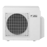
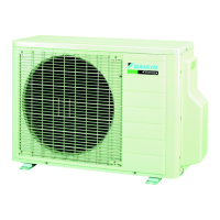
Details the specifications and functions of the outdoor unit.
Provides detailed technical specifications for the product series.
Detailed specifications for various indoor unit types.
Detailed specifications for various outdoor unit types.
Wiring diagrams for various indoor unit types and their components.
Connector wiring diagram for specific indoor unit models.
Wiring diagram for FTXR series indoor units.
Wiring diagram for FVXS series indoor units.
Wiring diagram for CDMQ/FDMQ series indoor units.
Wiring diagram for FFQ series indoor units.
Details the wiring for the FFQ series sensor kit.
Wiring for the BRYQ60A2W(S) sensor kit.
Wiring information for wired remote controllers.
Wiring diagram for the BRC1E73 wired remote controller.
Wiring for the FDMQ series wireless receiver.
Wiring for the BRC082A43 wireless receiver.
Wiring for the FFQ series wireless kits.
Wiring for BRC082A41W/BRC082A42W(S) wireless kits.
Contains wiring diagrams for outdoor units.
Wiring diagrams for specific outdoor unit models.
Wiring diagrams for specific outdoor unit models.
Explains basic functions applicable to all models.
Details how temperature is controlled and defined.
Explains the inverter principle and frequency control.
Describes functions specific to wall-mounted and floor-standing units.
Explains how airflow direction is managed.
Details fan speed settings and control methods.
Explains the dry operation mode for humidity removal.
Describes how the system automatically switches between cooling and heating.
Details how thermostat control functions based on temperature differences.
Explains the mode for comfortable nighttime operation and energy saving.
Describes the energy-saving ECONO operation mode.
Explains the dual-zone sensor operation for energy saving and comfort.
Details the sensor-based operation for energy saving.
Explains the operation for maximum cooling/heating capacity.
Describes the function of the indicator lamps.
Instructions for setting the clock on the remote controller.
Details how to set weekly timer schedules.
Covers additional functions not categorized elsewhere.
Prevents cold air blast during heating startup.
Indicates signal reception status.
Explains the use of the manual ON/OFF switch.
Restarts operation automatically after a power failure.
Describes functions specific to duct-concealed and ceiling cassette units.
Explains airflow direction management for these unit types.
Details fan speed settings for these unit types.
Explains the dry operation mode for humidity removal.
Instructions for setting clock and calendar with BRC1E73 remote.
Details how to set schedule timers with BRC1E73 remote.
Explains setback function for unoccupied periods.
Details the operation and logic of the drain pump control.
Prevents cold air blast during heating startup.
Details how presence and floor sensors enhance operation.
Covers additional functions for these unit types.
Technical details on system control logic and specifications.
Explains the role and function of various thermistors in the system.
Describes the priority and order of operation modes.
Details how compressor frequency is controlled.
Explains controls during mode changes and startup.
Prevents cold air blast during heating startup.
Details the four-way valve switching mechanism.
Explains compensation for four-way valve operation.
Describes the 3-minute standby function.
Details functions to protect the compressor from overload.
Explains control based on discharge pipe temperature.
Details control based on input current to protect the inverter.
Explains protection against indoor heat exchanger freezing.
Freeze-up protection for specific series.
Freeze-up protection for CDMQ/FDMQ series.
Controls to prevent abnormal high pressure during heating.
Protects the system from abnormal high pressures.
Explains control of the outdoor fan under various conditions.
Protects the compressor from liquid refrigerant.
Details the defrosting process.
Controls frequency to prevent high pressure at low Hz.
Explains the control logic for electronic expansion valves.
Lists and describes various system malfunctions and their causes.
Detects malfunctions related to thermistors.
Detects and handles overcurrent and overload conditions.
Manages operation when refrigerant is low.
Prevents icing of the indoor heat exchanger.
Lists compatible remote controllers and their reference pages.
Details the functions and operation of the ARC452A21 remote controller.
Details the functions and operation of the ARC466A36 remote controller.
Details the functions and operation of the ARC466A21 remote controller.
Details the functions and operation of the BRC944B2 remote controller.
Details the functions and operation of the BRC1E73 wired remote controller.
Details the functions and operation of the BRC082A43 wireless remote controller.
Details the functions and operation of wireless remote controller kits.
Lists common problems and initial checks for diagnosis.
Guides troubleshooting based on indoor and outdoor unit LED indicators.
Troubleshooting steps for indoor unit LED indicators.
Troubleshooting steps for outdoor unit LED indicators.
Procedures for diagnosing system faults using remote controllers.
Service diagnosis procedures for ARC452 series remote controllers.
Service diagnosis procedures for ARC466 series remote controllers.
Service diagnosis for BRC1E73 wired remote controller.
Service diagnosis for wireless remote controllers.
Lists error codes displayed on remote controllers and their meanings.
Error codes for wall/floor standing units.
Error codes for duct/cassette units.
Error codes for outdoor units.
Detailed troubleshooting steps for specific unit types.
Troubleshooting steps for indoor unit PCB faults.
Troubleshooting for freeze-up and peak-cut controls.
Troubleshooting for indoor fan motor issues.
Troubleshooting for thermistor faults.
Troubleshooting for front panel mechanism issues.
Troubleshooting communication errors between units.
Troubleshooting unit compatibility mismatches.
Detailed troubleshooting for duct/cassette units.
Troubleshooting for indoor unit PCB faults in these types.
Troubleshooting for drain system issues.
Troubleshooting for fan motor issues in these types.
Troubleshooting for DC motor fan issues.
Troubleshooting for indoor fan PCB faults.
Troubleshooting for humidifier-related issues.
Troubleshooting for thermistor faults in these types.
Troubleshooting for sensor abnormalities.
Troubleshooting for remote controller thermistor issues.
Troubleshooting communication errors between units.
Troubleshooting communication errors with remote controller.
Troubleshooting communication between multiple remote controllers.
Troubleshooting unit compatibility mismatches.
Detailed troubleshooting for outdoor unit issues.
Troubleshooting steps for refrigerant shortage.
Troubleshooting voltage detection issues.
Troubleshooting for unexecuted wiring error checks.
Troubleshooting voltage issues and anti-icing in other rooms.
Prevents icing of the indoor heat exchanger.
Troubleshooting for outdoor unit PCB faults.
Troubleshooting high pressure switch activation.
Troubleshooting compressor overload issues.
Troubleshooting for compressor lock conditions.
Troubleshooting for DC fan lock errors.
Troubleshooting for input overcurrent conditions.
Troubleshooting four-way valve issues.
Troubleshooting related to discharge pipe temperature.
Troubleshooting high pressure control during cooling.
Troubleshooting compressor sensor system issues.
Troubleshooting position sensor abnormalities.
Troubleshooting thermistor issues in outdoor units.
Troubleshooting electrical box temperature rise.
Troubleshooting radiation fin temperature rise.
Troubleshooting output overcurrent conditions.
Procedures for checking various components and systems.
Procedure for checking thermistor resistance values.
Steps to check the indoor fan motor connector.
Procedure to check power supply waveform integrity.
Steps to check the electronic expansion valve functionality.
Procedure to verify the four-way valve performance.
Checks related to the inverter unit's refrigerant system.
Procedure for using an inverter analyzer for diagnosis.
Steps to check the outdoor fan motor.
Checks installation parameters for proper operation.
Procedure to check discharge pressure.
Checks the overall outdoor fan system.
Checks the main circuit for short circuits.
Procedure for checking capacitor voltage.
Steps to check the power module.
Procedure for pump down operation during relocation or disposal.
Steps to perform forced cooling operation.
Explains the wiring error check function.
Procedures for conducting trial operation.
Trial operation steps for wall/floor standing units.
Trial operation steps for duct/cassette units.
Information on setting field parameters for various units.
Field settings for wall/floor standing units.
Settings for different indoor unit models.
How to select Celsius or Fahrenheit for display.
Setting addresses when multiple units are in one room.
Configuration details for jumpers and switches.
Field settings for duct/cassette units.
Steps to modify field settings using the remote controller.
Field settings overview for FFQ series.
Field settings overview for CDMQ/FDMQ series.
Setting MAIN/SUB for multiple wired remote controllers.
MAIN/SUB and address settings for wireless controllers.
MAIN/SUB and address settings for wireless FFQ controllers.
Field settings for outdoor unit configurations.
How to set priority for specific rooms.
How to lock the unit to cooling or heating mode.
Setting up the NIGHT QUIET mode for reduced noise.
Adjusting airflow for warmer discharge in heating.
Field settings for the drain pan heater.
Contains diagrams illustrating refrigerant piping for units.
Piping diagrams for indoor units.
Piping diagrams for outdoor units.
Contains diagrams illustrating electrical wiring for units.
Wiring diagrams for indoor units.
Wiring diagrams for outdoor units.
Information on the operational limits of the system.
| Series | 2MXS-W |
|---|---|
| Energy Efficiency Rating | A++/A+ |
| Refrigerant | R32 |
| Power Supply | 220-240 V, 50 Hz |
| Outdoor Unit Dimensions (WxHxD) | 765 x 550 x 285 mm |
| Noise Level (Indoor Unit) | 19 dB(A) - 42 dB(A) |


