EasyManua.ls Logo

Daikin 2MXU40GV1B User Manual

Daikin 2MXU40GV1B
274 pages
To Next Page IconTo Next Page
Page #1 background imageLoading...
Page #1 background image
Warning
Daikin Industries, Ltd.’s products are manufactured for export to numerous countries throughout the
world. Daikin Industries, Ltd. does not have control over which products are exported to and used in a
particular country. Prior to purchase, please therefore confirm with your local authorised importer,
distributor and/or retailer whether this product conforms to the applicable standards, and is suitable for
use, in the region where the product will be used. This statement does not purport to exclude, restrict
or modify the application of any local legislation.
Ask a qualified installer or contractor to install this product. Do not try to install the product yourself.
Improper installation can result in water or refrigerant leakage, electrical shock, fire or explosion.
Use only those parts and accessories supplied or specified by Daikin. Ask a qualified installer or
contractor to install those parts and accessories. Use of unauthorised parts and accessories or
improper installation of parts and accessories can result in water or refrigerant leakage, electrical
shock, fire or explosion.
Read the User's Manual carefully before using this product. The User's Manual provides important
safety instructions and warnings. Be sure to follow these instructions and warnings.
If you have any enquiries, please contact your local importer, distributor and/or retailer.
1. Air conditioners should not be installed in areas where corrosive gases, such as acid gas or alkaline gas, are produced.
2. If the outdoor unit is to be installed close to the sea shore, direct exposure to the sea breeze should be avoided. If you need to install
the outdoor unit close to the sea shore, contact your local distributor.
Cautions on product corrosion
JMI-0107 JQA-1452
Organization:
DAIKIN INDUSTRIES, LTD.
AIR CONDITIONING MANUFACTURING DIVISION
Scope of Registration:
THE DESIGN/DEVELOPMENT AND MANUFACTURE OF
COMMERCIAL AIR CONDITIONING, HEATING, COOLING,
REFRIGERATING EQUIPMENT, COMMERCIAL HEATING
EQUIPMENT, RESIDENTIAL AIR CONDITIONING
EQUIPMENT, HEAT RECLAIM VENTILATION, AIR
CLEANING EQUIPMENT, MARINE TYPE CONTAINER
REFRIGERATION UNITS, COMPRESSORS AND VALVES.
Organization:
DAIKIN INDUSTRIES
(THAILAND) LTD.
Scope of Registration:
THE DESIGN/DEVELOPMENT
AND MANUFACTURE OF AIR
CONDITIONERS AND THE
COMPONENTS INCLUDING
COMPRESSORS USED FOR THEM
All of the Daikin Group’s business
facilities and subsidiaries in Japan
are certified under the ISO 14001
international standard for
environment management.
Dealer
Head Office:
Umeda Center Bldg., 2-4-12, Nakazaki-Nishi,
Kita-ku, Osaka, 530-8323 Japan
Tokyo Office:
JR Shinagawa East Bldg., 2-18-1, Konan,
Minato-ku, Tokyo, 108-0075 Japan
http://www.daikin.com/global_ac/
All rights reserved
c
SiBE12-908
Specifications, designs and other content appearing in this brochure are current as of June 2009 but subject to change without notice.
SiBE12-908
Printed in Japan 06/2009 B AK
SiBE12-908
[Applied Models]
Inverter Multi : Heat Pump
Service Manual / Inverter Multi System with Humidifying G-Series
Inverter Multi System
with Humidifying
G-Series

Table of Contents

Other manuals for Daikin 2MXU40GV1B

Question and Answer IconNeed help?

Do you have a question about the Daikin 2MXU40GV1B and is the answer not in the manual?

Daikin 2MXU40GV1B Specifications

General IconGeneral
Model2MXU40GV1B
CategoryHeat Pump
ManufacturerDaikin
Cooling Capacity4.0 kW
Maximum Pipe Length30 m
Maximum Height Difference15 m
Power Supply220-240V, 50Hz
Outdoor Unit Dimensions (HxWxD)550 x 765 x 285 mm

Summary

Service Manual / Inverter Multi System with Humidifying G-Series

Introduction to the Daikin G-Series Multi System

Details various safety precautions for workers and users to prevent accidents.

Used Icons Guide

Explains the meaning of various icons used in the manual for attracting attention.

Part 1 List of Functions

System Functions Overview

Lists all available functions of the air conditioning system.

Part 2 Specifications

Indoor Unit Specifications

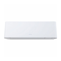
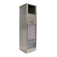
Lists specifications for various indoor unit models.

Outdoor Unit Specifications

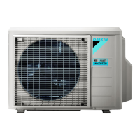
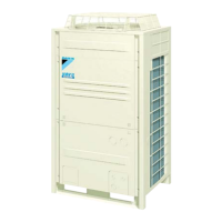
Lists specifications for various outdoor unit models.

Part 3 Printed Circuit Board Connector Wiring Diagram

Indoor Unit Wiring Diagrams

Wiring diagrams for indoor unit PCBs and connectors.

Outdoor Unit Wiring Diagrams

Wiring diagrams for outdoor unit PCBs and connectors.

Part 4 Function and Control

Main System Functions

Explains core functions of the air conditioning system.

HUMID HEAT Operation Details

Explains the humidification function during heating operation.

Intelligent Eye Sensor Operation

Explains the human motion sensor for energy saving and airflow control.

Control Specifications Overview

Details the hierarchy of operation modes including normal and forced modes.

Function of Thermistor

Heat Pump Model Thermistor Functions

Explains the role of thermistors in heat pump models for temperature control.

Control Specification

Mode Hierarchy Explanation

Details the hierarchy of operation modes including normal and forced modes.

Frequency Control Mechanism

Describes how frequency is determined based on room temperature differences.

Part 5 Installation / Operation Manual

Installation Manual Procedures

Covers procedures for installing the indoor and outdoor units.

Operation Manual Guide

Covers how to operate the air conditioning system.

Test Run and Final Check

Performing Test Runs and Final Checks

Details the procedure for performing test runs and final checks.

Essential Items for Checking

Lists essential items to check during test runs and final inspections.

Refrigerant Piping Work

Refrigerant Piping Installation Steps

Details the critical steps for refrigerant piping installation.

Pump Down Operation

Forced Cooling Procedure for Pump Down

Explains how to perform forced cooling for pump down.

Connecting the Humidifying Hose

Indoor Unit Humidifying Hose Connection

Provides instructions for connecting the humidifying hose to the indoor unit.

Outdoor Unit Humidifying Hose Connection

Provides instructions for connecting humidifying hoses to the outdoor unit.

Wiring

Electrical Wiring Procedures

Details the electrical wiring procedures for connecting units.

Drain Piping Installation

Covers the procedures for installing the drain piping.

Part 6 Service Diagnosis

Service Check Functions

Details methods for diagnosing failures using indicator lamps and LEDs.

Troubleshooting Common Issues

Lists error codes and troubleshooting steps for common problems.

Part 7 Removal Procedure

Indoor Unit Removal Steps

Provides step-by-step instructions for removing indoor unit components.

Outdoor Unit Removal Steps

Details the procedures for removing outdoor unit components.

Part 9 Appendix

Piping Diagrams

Provides piping diagrams for indoor and outdoor units.

Wiring Diagrams

Provides wiring diagrams for indoor and outdoor units.

Related product manuals