EasyManua.ls Logo

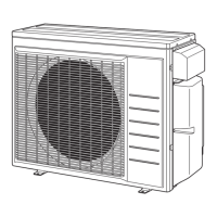
Daikin 3MXS24RMVJU Service Manual

Daikin 3MXS24RMVJU
282 pages
To Next Page IconTo Next Page
Page #1 background imageLoading...
Page #1 background image
Service
Manual
2MXS-N, 3/4MXS-R Series
SiUS121736EA
[Applied Models]
z Inverter Multi : Heat Pump
Multi-Split Type Air Conditioners

Table of Contents

Other manuals for Daikin 3MXS24RMVJU

Questions and Answers:

Daikin 3MXS24RMVJU Specifications

General IconGeneral
CategoryAir Conditioner
RefrigerantR-32
Number of Connectable Indoor Units3
Cooling Capacity24000 BTU/h
Heating Capacity27000 BTU/h
Indoor Unit Noise Level19 dB

Summary

Safety Cautions

Warnings and Cautions Regarding Safety of Workers

Essential safety guidelines for personnel involved in repair work.

Warnings and Cautions Regarding Safety of Users

Critical safety instructions for end-users to prevent injury or damage.

Icons Used

Icons Used

Explanation of symbols used throughout the manual to convey information.

Part 1 List of Functions

RA Indoor Unit

Details the functions available for RA Indoor Unit models.

SA Indoor Unit

Details the functions available for SA Indoor Unit models.

Outdoor Unit

Details the functions available for the Outdoor Unit.

Part 2 Specifications

RA Indoor Unit

Technical specifications for various RA Indoor Unit models.

SA Indoor Unit

Technical specifications for various SA Indoor Unit models.

Outdoor Unit

Technical specifications for various Outdoor Unit models.

Part 3 Printed Circuit Board Connector Wiring Diagram

Indoor Unit

Wiring diagrams for various indoor unit models and their components.

Sensor Kit for FFQ Series

Wiring details for the sensor kit used with FFQ series units.

Wired Remote Controller

Wiring information for wired remote controllers like BRC1E73.

Wireless Remote Controller Receiver for FDMQ series

Wiring details for wireless receiver modules used with FDMQ series.

Wireless Remote Controller Kit for FFQ Series

Wiring details for wireless remote controller kits used with FFQ series.

Outdoor Unit

Wiring diagrams for the outdoor unit and its main PCB.

Part 4 Functions and Control

Common Functions

General functions applicable across multiple unit types.

RA Indoor Unit Functions

Details specific functions and operations for RA Indoor Unit models.

SA Indoor Unit Functions

Details specific functions and operations for SA Indoor Unit models.

Control Specification

Detailed explanation of the system's control logic and parameters.

Part 5 Remote Controller

Applicable Remote Controller

Lists compatible remote controller models for various indoor units.

ARC466A36

Detailed explanation and operation of the ARC466A36 remote controller.

ARC452A21

Detailed explanation and operation of the ARC452A21 remote controller.

ARC452A23

Detailed explanation and operation of the ARC452A23 remote controller.

ARC466A21

Detailed explanation and operation of the ARC466A21 remote controller.

Wired Remote Controller (BRC944B2)

Operation and features of the BRC944B2 wired remote controller.

Wired Remote Controller (BRC1E73)

Operation and features of the BRC1E73 wired remote controller.

Wireless Remote Controller (BRC082A43)

Operation and features of the BRC082A43 wireless remote controller.

Wireless Remote Controller (BRC082A41W, BRC082A42W(S))

Operation and features of the BRC082A41W/BRC082A42W(S) wireless controllers.

Part 6 Service Diagnosis

General Problem Symptoms and Check Items

Lists common problems and initial checks for troubleshooting.

Troubleshooting with LED

Guides troubleshooting based on LED indicators on indoor and outdoor units.

Service Diagnosis

Diagnostic procedures for RA and SA Indoor Units.

Code Indication on Remote Controller

Explains error codes displayed on remote controllers for RA and SA units.

Troubleshooting for RA Indoor Unit

Detailed troubleshooting steps for various RA Indoor Unit errors.

Troubleshooting for SA Indoor Unit

Detailed troubleshooting steps for various SA Indoor Unit errors.

Troubleshooting for Outdoor Unit

Detailed troubleshooting steps for various Outdoor Unit errors.

Check

Procedures for checking electrical components and system parameters.

Part 7 Trial Operation and Field Settings

Field Settings

Procedures for configuring settings on Outdoor, RA, and SA Indoor Units.

Pump Down Operation

Procedure for safely removing refrigerant before relocation or disposal.

Forced Cooling Operation

Steps to perform forced cooling for testing purposes.

Wiring Error Check Function

Procedure to automatically check and correct wiring errors.

Trial Operation

Steps to perform trial operation on RA and SA Indoor Units.

Silicone Grease on Power Transistor/Diode Bridge

Guidelines for applying silicone grease during PCB replacement for heat dissipation.

Part 8 Appendix

Piping Diagrams

Visual representations of refrigerant piping for various indoor and outdoor units.

Wiring Diagrams

Electrical wiring schematics for indoor and outdoor units.

Operation Limit

Defines the operational limits for indoor and outdoor temperatures.

Related product manuals