9 | Electrical installation
Installer reference guide
50
2MXM-A9, 3MXM-A9, 4MXM-A9, 5MXM-A9
R32 Split series
4P600463-7G – 2022.09
AC
DC
DC
S20 S21 S22 S23
S92
S93
S40
S80
S70
U W
V
DC-
FU2
S90
S24
AL2 AL1
e
f
g
h
a
b
c
d
DC(-)
FU2
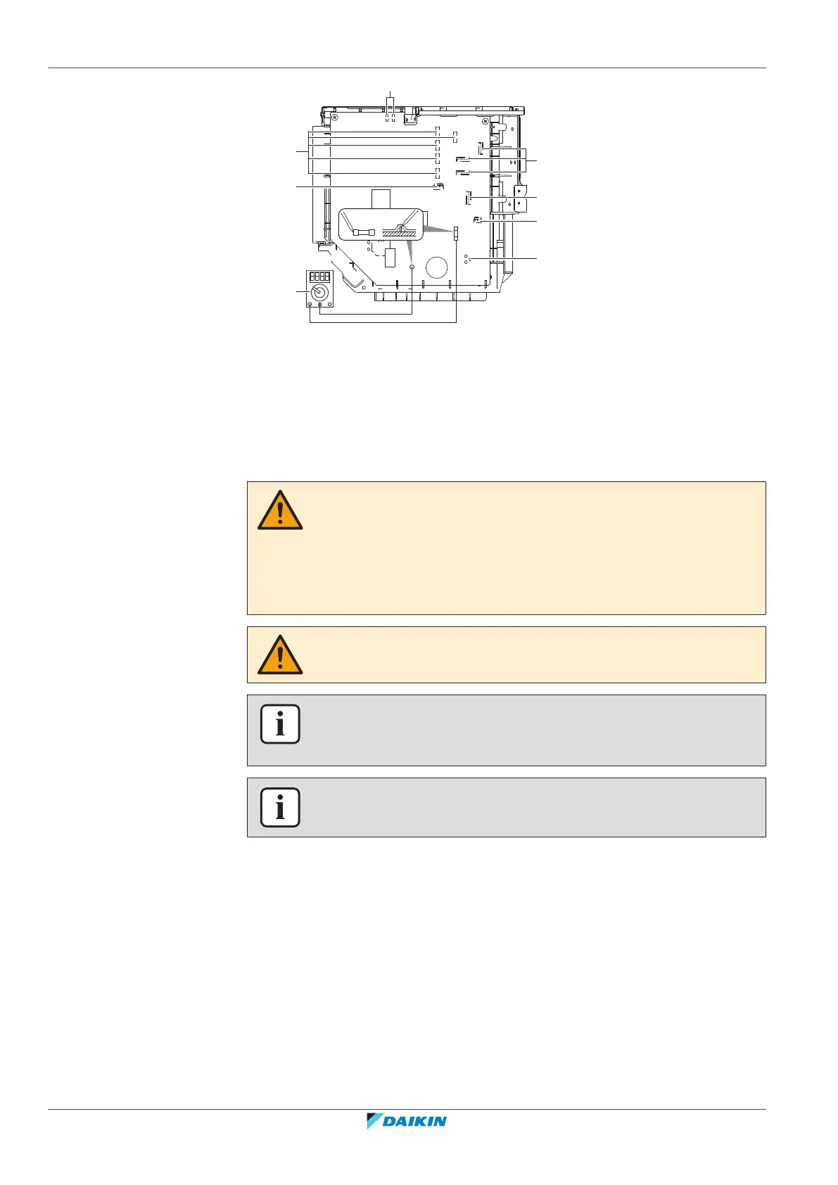
a AL1, AL2 - solenoid valve lead wire connector*
b S20~24 - electronic expansion valve coil lead wire connector (room A, B, C, D, E)*
c S40 – thermal overload relay lead wire and high pressure switch connector*
d Multimeter (DC voltage range)
e S90~93 – thermistor lead wire connector
f S70 - fan motor lead wire connector
g S80 - 4-way valve lead wire connector
h Compressor lead wire connector
*May differ depending on the model.
WARNING
▪ All wiring MUST be performed by an authorised electrician and MUST comply
with the applicable national wiring regulation.
▪ Make electrical connections to the fixed wiring.
▪ All components procured on-site and all electrical construction MUST comply
with the applicable legislation.
WARNING
ALWAYS use multicore cable for power supply cables.
INFORMATION
Also read the precautions and requirements in the "2 General safety
precautions"[47].
INFORMATION
Also read "9.1.3Specifications of standard wiring components"[453].



 To Next Page