
R
Roy GilbertSep 14, 2025
How to make setpoints display all the time on Daikin Programmable thermostat?
- JJane KellySep 14, 2025
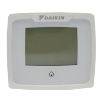
To make setpoints display all the time on Daikin Programmable thermostat, press the VIEW button six times.
How to make setpoints display all the time on Daikin Programmable thermostat?
To make setpoints display all the time on Daikin Programmable thermostat, press the VIEW button six times.
Lists core features like 7-Day programming, multiple systems, large display, Fahrenheit/Celsius, icon lights, relay outputs, WSHP alarm, remote sensor, and suitability for residential/commercial applications.
Explains the function of navigation buttons (Up/Down, Left/Right, Menu, Home, Fan, Schedule) and mode buttons.
Details electrical ratings, temperature control range, accuracy, anti-short cycle, backlight, DC power, and model configurations.
Describes the thermostat's function for heating, cooling, and auto changeover, including compressor protection and temporary holds.
Details the meaning of various icons (HUMIDITY, FAN, MODE, HOME, SCHEDULE, ALARM) and menu options (CONFIG, CLOCK, LOCK, VIEW).
Provides essential safety precautions regarding power, voltage, wiring, outdoor temperature limits for AC, and proper thermostat usage.
Outlines the step-by-step procedure for safely removing an existing thermostat, including power disengagement and wire labeling.
Details steps for mounting the sub-base, drilling, anchoring, and connecting wires to terminals, ensuring proper wire handling.
Defines the purpose of each terminal (e.g., A, C, W1, Y1) and shows a diagram of thermostat connections to the unit controller.
Illustrates the specific wiring connections for models 910193093 and 910193126 between the controller terminal TB2 and the touch screen.
Shows the wiring diagrams for models 910193127 and 910193128, including connections to the controller terminal TB2 and expansion modules.
Details the wiring diagram for model 910193129, illustrating connections to the controller terminal TB2 and expansion module TB1.
Provides instructions for mounting and wiring a remote sensor to the S1 and SC terminals on the thermostat and sensor.
Explains how to access and view remote sensor temperature readings on the thermostat display.
Lists the output terminal assignments for various system types (Heat Pump, Electric) for models 910193093 and 910193126.
Details the output terminal assignments for models 910193128 and 910193129, including humidity control configurations.
Explains the purpose of the configuration lock and the access screen for protected settings.
Provides step-by-step instructions for locking and unlocking the thermostat using the menu and specific buttons.
Outlines the procedure to modify the existing lock code for enhanced security.
Explains how to enter configuration mode and navigate through various setup screens using the thermostat's interface.
Details how to choose between Fahrenheit (F) and Celsius (C) for temperature display.
Explains how to set the temperature differentials for the first, second, and third stages of heating or cooling.
Describes how to configure outputs for heating/cooling to be staged off independently or simultaneously.
Covers heat source configuration, minimum deadband, and auxiliary delay settings for optimal system performance.
Explains settings for keypad lockout degree range and maximum/minimum heat and cool setpoints.
Details how to set specific cooling and heating setpoints for periods of vacation.
Describes how to adjust the room temperature offset for accurate readings.
Explains options for selecting the primary temperature sensor (on-board, remote, or averaged).
Covers fan delay off time and maximum cycles allowed per hour for system efficiency.
Details configuring the system for humidification or dehumidification, including specific conditions and codes.
Explains how to set the humidity differential and the conditions required to activate humidification or dehumidification.
Covers extended AC time for dehumidification and relay function settings for dehumidification.
Explains hourly cycle fan operation and how to enable the fan during specific scheduled periods.
Describes the filter monitoring feature and how to reset the elapsed run hours.
Provides step-by-step instructions for accurately setting the thermostat's internal clock and date.
Explains the functionality of the OFF, Heat, and Cool modes, including visual indicators like flame and snowflake icons.
Describes how the thermostat automatically switches between heating and cooling based on room temperature and setpoints.
Guides users on how to change the fan speed between AUTO, ON, and HOURLY modes, and between HI and LOW speeds.
Explains how to switch between high and low fan speeds while keeping the fan mode unchanged.
Details how the thermostat displays the current stages of heating or cooling using flashing icons.
Clarifies that the number of flashes of the flame or snowflake icon indicates the current heating or cooling stages.
Describes how to return to the sleep screen where indicator icons do not flash.
Outlines the steps for testing the heating and cooling functions, including temperature adjustments and observing system response.
Explains how to perform a test on the fan operation by setting it to ON and AUTO modes.
Introduces the programmable periods (WAKE, LEAVE, RETURN, SLEEP) and daily customization.
Provides detailed instructions for setting the program schedule, including day, period, time, and temperature configurations.
Explains how to access various view screens for remote sensor data, date/time, lock status, and filter status.
Details options for controlling the display of setpoints, fan status, and program information.
Explains how to temporarily override the programmed schedule for a set duration or until the next transition.
Guides on setting the vacation timer and entering the return date/time for vacation mode.
Details the procedure for clearing unit fault alarms that illuminate on the thermostat after the condition is resolved.
Displays the thermostat's default schedule with pre-set WAKE, LEAVE, RETURN, and SLEEP times and temperatures.
Offers a template for users to record their custom program schedule settings for each day of the week.
Addresses issues like no display, fan not running, and button response problems.
Covers problems with program schedule timing, frequent on/off cycles, and failure to follow the program.
Addresses continuous fan operation, incorrect temperature readings, LOCK indicators, and missing display information.
Deals with issues related to heat/cool not engaging, remote sensor errors, override status, and setpoint display problems.
Outlines the terms of the five-year limited warranty, including what is covered and what is excluded.
Details the buyer's responsibilities and procedures for submitting and managing warranty claims.
| Product Type | Programmable Thermostat |
|---|---|
| Color | White |
| Model Number | 910193093 |
| Brand | Daikin |
| Display Type | Digital |
| Programmability | 7-Day Programmable |
| Backlight | Yes |
| Hold Function | Yes |
| Filter Change Indicator | Yes |
| Category | Programmable Thermostats |
| Compatibility | Most HVAC systems |
| Power Source | Battery-powered |
| System Mode | Heat, Cool, Auto, Off |
| Fan Mode | On, Auto |