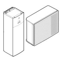
Do you have a question about the Daikin ARX35JV1B and is the answer not in the manual?
Details safety precautions for repair work, classified into Warning and Caution categories.
Explains the meaning of various icons used to draw attention to specific information.
Lists and categorizes the various functions available for the air conditioning units.
Provides detailed technical specifications for indoor and outdoor units, including capacity, power, and dimensions.
Details the control PCB and display PCB component layout and connector identification.
Details the main PCB and filter PCB component layout and connector identification.
Explains core operational functions like temperature control, frequency principle, and fan speed settings.
Describes the role and function of various thermistors in controlling the air conditioning system.
Details control specifications, including mode hierarchy, frequency control, and specific control logic.
Guides on diagnosing issues by observing the operation lamp and service monitor LEDs.
Lists common unit symptoms and provides corresponding checks and measures for diagnosis.
Provides detailed troubleshooting steps for specific error codes, including causes and solutions.
Outlines specific checks for components like thermistors, fan motors, and power modules.
Covers essential servicing procedures like pump down and forced cooling operations.
Details the steps for performing a trial operation after installation or repair to verify functionality.
Explains how to configure settings, such as address setting for multiple units and jumper configurations.
Illustrates the refrigerant piping layout for indoor and outdoor units.
Presents the electrical wiring diagrams for both indoor and outdoor units, showing component connections.
References specific booklets for detailed removal and installation procedures for various models.
| Model | ARX35JV1B |
|---|---|
| Category | Heat Pump |
| Manufacturer | Daikin |
| Cooling Capacity | 3.5 kW |
| Heating Capacity | 4.0 kW |
| Power Supply | 220-240V, 50Hz |
| Refrigerant | R410A |
| Outdoor Unit Noise Level | 48 dB(A) |
| Energy Efficiency Ratio (EER) | 3.21 |
| Energy Efficiency Class (Cooling) | A++ |
| Indoor Unit Weight | 9 kg |


