Do you have a question about the Daikin ARX25JV1B and is the answer not in the manual?
Essential safety warnings and guidelines for handling and operating the equipment.
Explanation of symbols used to convey important information within the manual.
Categorized list of all available functions for the indoor and outdoor units.
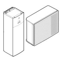
Detailed technical specifications for the indoor unit models.
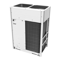
Detailed technical specifications for the outdoor unit models.
Wiring diagrams and component identification for indoor unit PCBs.
Wiring diagrams and component identification for outdoor unit PCBs.
Explanation of core operational functions like temperature control and fan speed.
Details on how thermistors are used for system control and monitoring.
Technical details on control logic, modes, and specifications.
Diagnosing issues based on LED indicators on the indoor and outdoor units.
Table of common operational problems and suggested troubleshooting steps.
Procedures for accessing and using diagnostic modes on the remote controller.
Detailed explanations and troubleshooting flows for various error codes.
Step-by-step checks for components like thermistors, motors, and valves.
Operational tips for pump down and forced cooling during maintenance.
Steps for performing a trial operation after installation or repair.
Configuration settings for specific installation scenarios and jumpers.
Proper application of silicon grease for heat dissipation on PCBs.
Visual representation of refrigerant piping for indoor and outdoor units.
Electrical wiring schematics for indoor and outdoor units.
References to separate booklets for unit disassembly and reassembly.
| Model | ARX25JV1B |
|---|---|
| Category | Heat Pump |
| Manufacturer | Daikin |
| Cooling Capacity (kW) | 2.5 |
| Heating Capacity (kW) | 3.2 |
| Power Supply (V/Ph/Hz) | 220-240/1/50 |
| Rated Cooling Power Input (kW) | 0.67 |
| Energy Efficiency Ratio (EER) Cooling | 3.73 |
| Outdoor Unit Noise Level (dB(A)) | 46 |
| Indoor Unit Weight (kg) | 9 |
| Refrigerant | R32 |
| Indoor Unit Noise Level (dB(A)) | 37 |
| Outdoor Unit Dimensions (HxWxD, mm) | 550x800x285 |