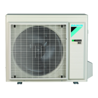
5 Piping installation
Installation manual
8
ARXF50+60A5V1B + (A)RXF71A5V1B + RXF50+60B5V1B +
RXP50~71M5V1B + (A)RXM50+60R5V1B + ARXM71R5V1B +
RXM42R5V1B
R32 split series
3P645642-1A – 2021.03
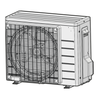
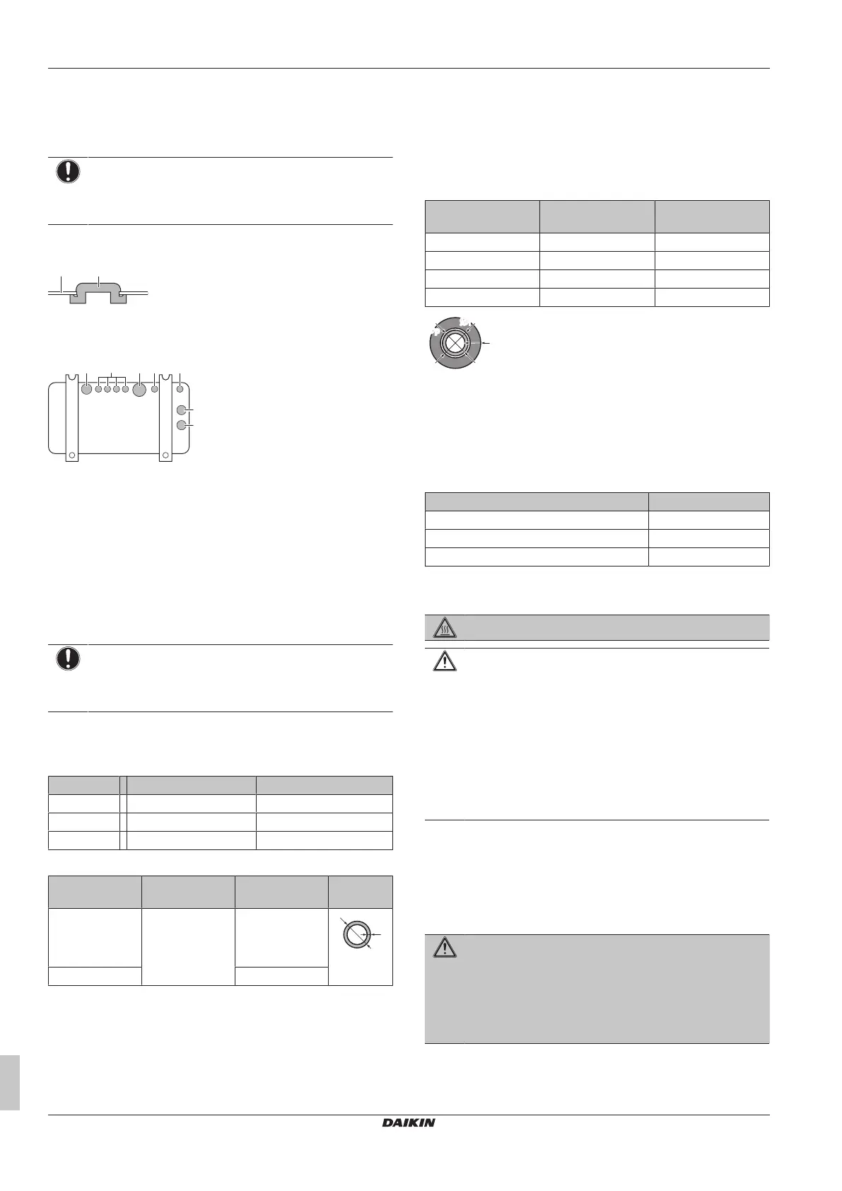
c Drain plug
d Hose (field supply)
To close the drain holes and attach the drain
socket
NOTICE
In cold areas, do NOT use a drain socket, hose and caps
(1, 2) with the outdoor unit. Take adequate measures so
that the evacuated condensate CANNOT freeze.
1 Install drain caps 1 and 2 (accessory). Make sure the edges of
the drain caps close off the holes completely.
a Bottom frame
b Drain cap
2 Install the drain socket.
a Drain hole. Install a drain cap (2).
b Drain hole. Install a drain cap (1).
c Drain hole for drain socket
5 Piping installation
5.1 Preparing refrigerant piping
5.1.1 Refrigerant piping requirements
NOTICE
The piping and other pressure-containing parts shall be
suitable for refrigerant. Use phosphoric acid deoxidised
seamless copper for refrigerant.
▪ Piping material: Phosphoric acid deoxidised seamless copper.
▪ Flare connections: Only use annealed material.
▪ Piping diameter:
Models Liquid piping Gas piping
ARXM71R Ø9.5mm (3/8") Ø15.9 mm (5/8")
RXM42R Ø6.4mm (1/4") Ø9.5mm (3/8")
Other Ø6.4mm (1/4") Ø12.7mm (1/2")
▪ Piping temper grade and thickness:
Outer diameter
(Ø)
Temper grade Thickness (t)
(a)
6.4mm (1/4")
9.5mm (3/8")
12.7mm (1/2")
Annealed (O) ≥0.8mm
15.9mm (5/8") ≥1mm
(a)
Depending on the applicable legislation and the maximum
working pressure of the unit (see "PS High" on the unit name
plate), larger piping thickness might be required.
5.1.2 Refrigerant piping insulation
▪ Use polyethylene foam as insulation material:
▪ with a heat transfer rate between 0.041 and 0.052W/mK (0.035
and 0.045kcal/mh°C)
▪ with a heat resistance of at least 120°C
▪ Insulation thickness
Pipe outer diameter
(Ø
p
)
Insulation inner
diameter (Ø
i
)
Insulation thickness
(t)
6.4mm (1/4") 8~10mm ≥10mm
9.5mm (3/8") 10~14mm ≥13mm
12.7mm (1/2") 14~16mm ≥10mm
15.9mm (5/8") 16~20mm ≥13mm
If the temperature is higher than 30°C and the humidity is higher
than RH80%, the thickness of the insulation materials should be at
least 20 mm to prevent condensation on the surface of the
insulation.
5.1.3 Refrigerant piping length and height
difference
What? Distance
Maximum allowable pipe length 30m
Minimum allowable pipe length 3m
Maximum allowable height distance 20m
5.2 Connecting the refrigerant piping
DANGER: RISK OF BURNING/SCALDING
CAUTION
▪ No brazing or welding on site for units with R32
refrigerant charge during shipment.
▪ During installation of the refrigeration system, joining of
parts with at least one part charged shall be performed
taking into account the following requirements: inside
occupied spaces non permanent joints are not allowed
for R32 refrigerant except for site made joints directly
connecting the indoor unit to piping. Site made joints
directly connecting piping to indoor units shall be of non
permanent type.
5.2.1 To connect the refrigerant piping to the
outdoor unit
▪ Piping length. Keep field piping as short as possible.
▪ Piping protection. Protect the field piping against physical
damage.
WARNING
Connect the refrigerant piping securely before running the
compressor. If the refrigerant piping is NOT connected and
the stop valve is open when the compressor is run, air will
be sucked in. This will cause abnormal pressure in the
refrigeration cycle, which may result in equipment damage
and even injury.