S
Sabrina RossAug 19, 2025
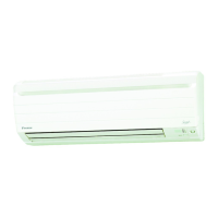
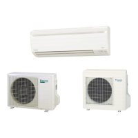
Why is my Daikin Air Conditioner cooling/heating effect poor?
- NNancy WrightAug 20, 2025
If your Daikin Air Conditioner isn't cooling or heating well, several factors could be the cause. First, check if the air filters are clean. Also, ensure that nothing is blocking the air inlet or outlet of either the indoor or outdoor units. Verify that the temperature setting is appropriate for your needs and that all windows and doors are properly closed. Finally, make sure the airflow rate and air direction are correctly set, and check whether the unit is set to INTELLIGENT EYE mode.