AZQS100~140B7V1B+Y1B
Split system air conditioners
4P332194-1B – 2015.01
Installation manual
16
16. Wiring diagram
A1P~A5P............... Printed circuit board
BS1~BS4............... Push button switch
C1~C4 ................... Capacitor
DS1........................ DIP switch
E1H........................ Bottomplate heater (option)
F1U~F11U ............. Fuse
H1P~H7P .............. Light emitting diode (service monitor orange)
H2P: prepare, test when flickering
H2P: malfunction detection when light up
HAP ....................... Light emitting diode (service monitor green)
K1M ....................... Magnetic contactor
K11M ..................... V1B: Magnetic contactor
K1R (A1P) ............. Magnetic relay (Y1S)
K2R (A1P) ............. Y1B: Magnetic relay (E1H) (option)
K2R~K4R .............. Y1B: Magnetic relay
K4R (A1P) ............. V1B: Magnetic relay (E1H) (option)
K10R...................... V1B: Magnetic relay
L1R~L5R ............... Reactor
M1C....................... Motor (compressor)
M1F ....................... Motor (fan) (upper)
M2F ....................... Motor (fan) (lower)
PS.......................... Switching power supply
Q1DI ...................... Earth leakage circuit breaker (30 mA)
R1~R4 ................... Resistor
R1T........................ Thermistor (air)
R2T........................ Thermistor (discharge)
R3T........................ Thermistor (suction)
R4T........................ Thermistor (heat exchanger)
R5T........................ Thermistor (heat exchanger middle)
R6T........................ Thermistor (liquid)
R10T...................... Thermistor (fin)
RC ......................... V1B: Signal receiver circuit
S1PH ..................... High pressure switch
TC.......................... V1B: Signal transmission circuit
V1R........................ IGBT power module
V1T........................ V1B: Insulated gate bipolar transistor (IGBT)
V2R........................ V1B: Diode module
V2R........................ IGBT power module
X1M ....................... Terminal (power supply) strip
X1Y........................ V1B: Optional connector
X6A........................ Y1B: Optional connector
Y1E........................ Electronic expansion valve
Y1S........................ Solenoid 4-way valve
Z1C~Z7C............... Noise filter (ferrite core)
Z1F~Z4F................ Noise filter
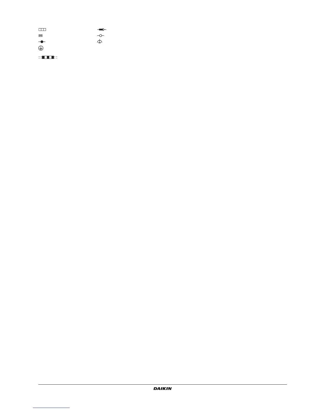
: Terminal strip : Relay connector
: Connector : Terminal
: Connection : Noiseless earth
: Protective earth
(screw)
L : Live
: Field wiring N : Neutral
BLK : Black ORG : Orange
BLU : Blue RED : Red
BRN : Brown WHT : White
GRN : Green YLW : Yellow
Notes
: This wiring diagram only applies to the outdoor unit
: Refer to the combination table and option manual for
connecting wiring to X6A, X28A, X77A, X800M
: Refer to the wiring diagram sticker (on back of front plate) on
how to use BS1~BS4 and DS1 switch
: Do not operate the unit by short-circuiting protection device
S1PH
: Confirm the method of setting the selector switches (DS1) by
service manual.
Factory setting of all switches = "OFF".