7 Disposal
Installation manual
12
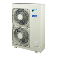
FNA25~60A2VEB(9)
Split system air conditioners
4P456958-1J – 2020.12
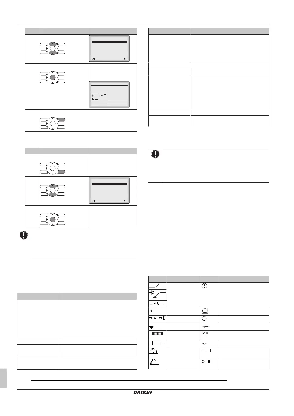
# Action Result
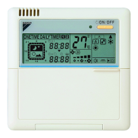
3 Select Test Operation.
Return Setting
Service Settings 1/3
Test Operation
Maintenance Contact
Field Settings
Demand
Min Setpoints Differential
Group Address
4 Press. Test Operation is
displayed on the home
menu.
Cool
Return Setting
Test Operation
5 Press within 10seconds. Test run starts.
3 Check operation for 3minutes.
4 Stop the test run.
# Action Result
1 Press at least 4seconds. The Service Settings menu
is displayed.
2 Select Test Operation.
Return Setting
Service Settings 1/3
Test Operation
Maintenance Contact
Field Settings
Demand
Min Setpoints Differential
Group Address
3 Press. The unit returns to normal
operation, and the home
menu is displayed.
NOTICE
When the indoor unit fan rotates and the operation light
flashes after trial operation, there is a risk of refrigerant
leakage. In that case, immediately ventilate the room and
contact your dealer.
(1)
6.3 Error codes when performing a
test run
If the installation of the outdoor unit has NOT been done correctly,
the following error codes may be displayed on the user interface:
Error code Possible cause
Nothing displayed
(the currently set
temperature is not
displayed)
▪ The wiring is disconnected or there is a
wiring error (between power supply and
outdoor unit, between outdoor unit and
indoor units, between indoor unit and
user interface).
▪ The fuse on the outdoor or indoor unit
PCB has blown.
A0 ▪ Refrigerant leak detected.
(1)
CH ▪ Abnormality of refrigerant leakage
sensor.
(1)
E3, E4 or L8 ▪ The stop valves are closed.
▪ The air inlet or air outlet is blocked.
Error code Possible cause
E7 There is a missing phase in case of three-
phase power supply units.
Note: Operation will be impossible. Turn
OFF the power, recheck the wiring, and
switch two of the three electrical wires.
L4 The air inlet or air outlet is blocked.
U0 The stop valves are closed.
U2 ▪ There is a voltage imbalance.
▪ There is a missing phase in case of
three-phase power supply units. Note:
Operation will be impossible. Turn OFF
the power, recheck the wiring, and switch
two of the three electrical wires.
U4 or UF The inter-unit branch wiring is not correct.
UA The outdoor and indoor unit are
incompatible.
7 Disposal
NOTICE
Do NOT try to dismantle the system yourself: dismantling
of the system, treatment of the refrigerant, oil and other
parts MUST comply with applicable legislation. Units
MUST be treated at a specialised treatment facility for
reuse, recycling and recovery.
8 Technical data
▪ A subset of the latest technical data is available on the regional
Daikin website (publicly accessible).
▪ The full set of latest technical data is available on the Daikin
Business Portal (authentication required).
8.1 Wiring diagram
8.1.1 Unified wiring diagram legend
For applied parts and numbering, refer to the wiring diagram on the
unit. Part numbering is by Arabic numbers in ascending order for
each part and is represented in the overview below by "*" in the part
code.
Symbol Meaning Symbol Meaning
Circuit breaker Protective earth
Connection Protective earth (screw)
Connector
Rectifier
Earth Relay connector
Field wiring Short-circuit connector
Fuse Terminal
Indoor unit Terminal strip
Outdoor unit Wire clamp
(1)
Only for units using R32 refrigerant. Refer to the outdoor unit specifications for the type of refrigerant to be used.