English 4
Do not place objects in direct proxim-
ity of the outdoor unit and do not let
leaves and other debris accumulate
around the unit.
Leaves are a hotbed for small animals
which can enter the unit. Once in the unit,
such animals can cause malfunctions,
smoke or fire when making contact with
electrical parts.
Turn off the power when the unit is not
to be used for long periods of time.
Otherwise, the unit may get hot or catch
on fire due to dust accumulation.
Never touch the internal parts of the
controller.
Do not remove the front panel. Touching
certain internal parts will cause electric
shocks and damage to the unit. Please
consult your dealer about checking and
adjustment of internal parts.
Do not leave the remote controller
wherever there is a risk of wetting.
If water gets into the remote controller
there is a risk of electrical leakage and
damage to electronic components.
When using the wireless remote con-
troller, do not put a strong light beam or
install an inverter fluorescent lamp near
the receiving section on the main unit.
A malfunction may occur.
Watch your steps at the time of air fil-
ter cleaning or inspection.
High-place work is required, to which
utmost attention must be paid.
If the scaffold is unstable, you may fall or
topple down, thus causing injury.
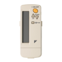
2. NAMES AND FUNCTIONS
OF THE OPERATING SEC-
TION (Refer to Fig. 1-1, 1-2,
2 on page [1])
1
DISPLAY “ ”
(SIGNAL TRANSMISSION)
This lights up when a signal is being
transmitted.
2
DISPLAY “ ” “ ” “ ” “ ”
“ ” (OPERATION MODE)
This display shows the current OPER-
ATION MODE. For cooling only type,
“ ” (AUTOMATIC) and “ ”
(HEATING) are not installed.
3
DISPLAY “ ” (SET TEMPERA-
TURE)
This display shows the set temperature.
4
DISPLAY “ ”
(PROGRAMMED TIME)
This display shows PROGRAMMED
TIME of the system start or stop.
5
DISPLAY “ ” (AIRFLOW FLAP)
Refer to page 10.
6
DISPLAY “ ” “ ” “ ” (FAN
SPEED)
The display shows the set fan speed.
7
DISPLAY “ ”
(INSPECTION/ TEST OPERATION)
When the INSPECTION/TEST OPER-
ATION BUTTON is pressed, the dis-
play shows the system mode is in.
Do not operate this button during nor-
mal use.
8
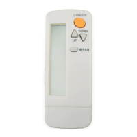
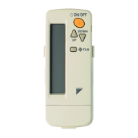
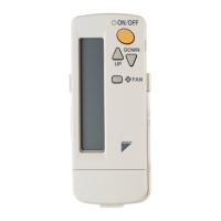
ON/OFF BUTTON
Press the button and the system will
start. Press the button again and the
system will stop.
MHL
C
hr.
hr.
TEST
01_EN_3P302565-1.fm Page 4 Monday, February 13, 2012 4:09 PM