English 4
Refer to the operation manual attached to the indoor
unit.
2. WHAT TO DO BEFORE OPERA-
TION
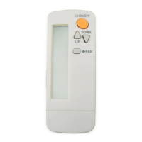
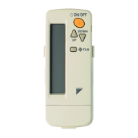
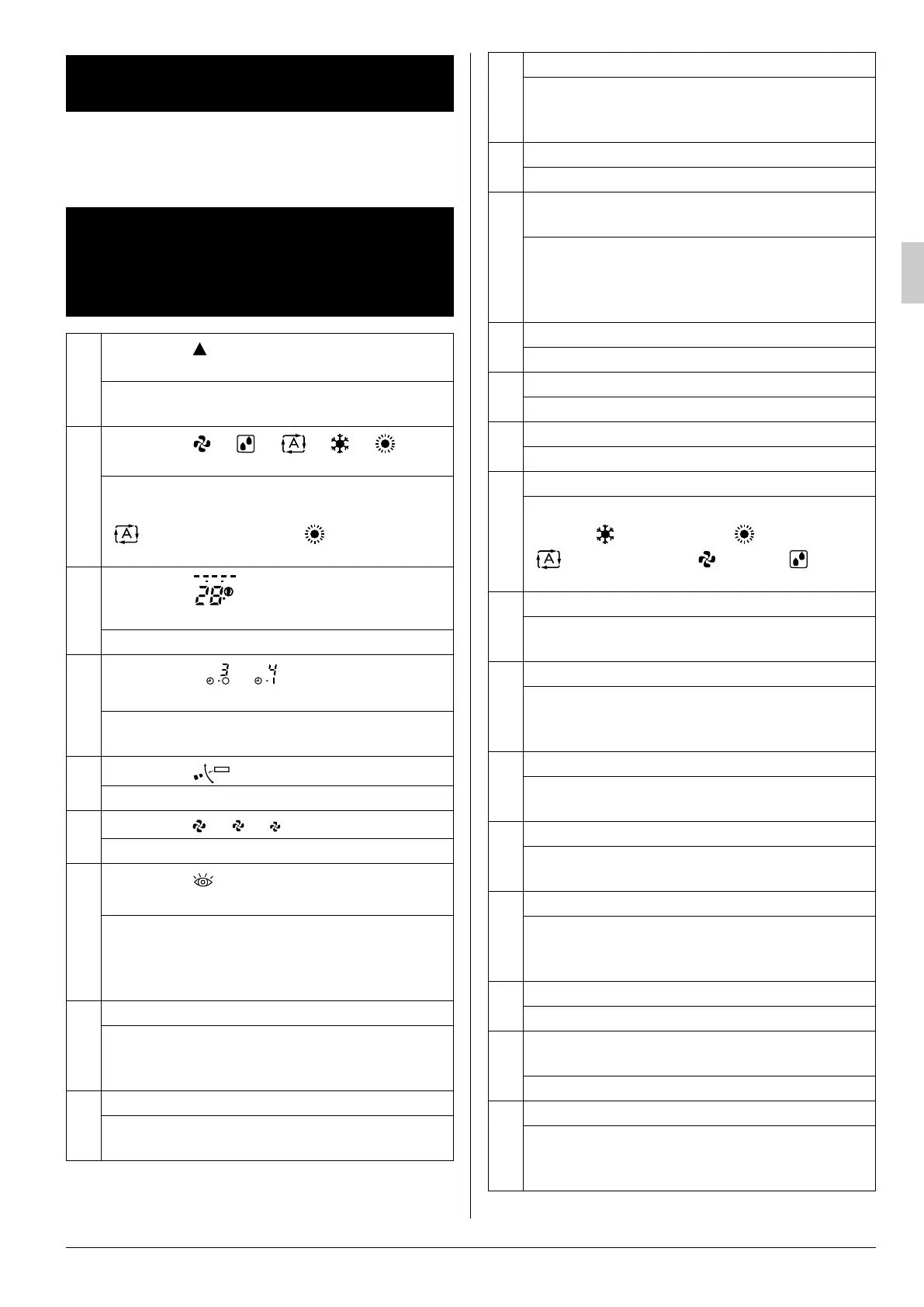
3. NAMES AND FUNCTIONS OF
THE OPERATING SECTION
(Refer to Fig. 1-1, 1-2, 2 on page
[1])
1
DISPLAY “ ”
(SIGNAL TRANSMISSION)
This lights up when a signal is being transmit-
ted.
2
DISPLAY “ ” “ ” “ ” “ ” “ ”
(OPERATION MODE)
This display shows the current OPERATION
MODE. For cooling only type (BRC7GA56),
“ ” (AUTOMATIC) and “ ” (HEATING)
are not installed.
3
DISPLAY “ ”
(SET TEMPERATURE)
This display shows the set temperature.
4
DISPLAY “ ”
(PROGRAMMED TIME)
This display shows PROGRAMMED TIME of
the air conditioner start or stop.
5
DISPLAY “ ” (HORIZONTAL BLADE)
Refer to page 8, 9.
6
DISPLAY “ ” “ ” “ ” (FAN SPEED)
The display shows the set fan speed.
7
DISPLAY “ ”
(INSPECTION/ TEST OPERATION)
When the INSPECTION/TEST OPERATION
BUTTON is pressed, the display shows the
system mode is in.
Do not operate this button during normal use.
8
ON/OFF BUTTON
Press the button and the air conditioner will
start. Press the button again and the air con-
ditioner will stop.
9
FAN SPEED CONTROL BUTTON
Press this button to select the fan speed, Low
or Middle or High, of your choice.
MHL
C
hr.
hr.
TEST
10
TEMPERATURE SETTING BUTTON
Use this button for SETTING TEMPERA-
TURE (Operates with the front cover of the
remote controller closed.)
11
SIGNAL TRANSMITTER
This sends the signals to the indoor unit.
12
TEMPERATURE ADJUSTMENT/
PROGRAMMING TIMER BUTTON
Use this button for temperature setting and
programming “START and/or STOP” time.
(Operates with the front cover of the remote
controller opened.)
13
TIMER MODE START/STOP BUTTON
Refer to page 10.
14
TIMER RESERVE/CANCEL BUTTON
Refer to page 10.
15
AIRFLOW DIRECTION ADJUST BUTTON
Refer to page 8, 9.
16
OPERATION MODE SELECTOR BUTTON
Press this button to select OPERATION
MODE. “ ” (COOLING), “ ” (HEATING),
“ ” (AUTOMATIC), “ ” (FAN), “ ” (PRO-
GRAM DRY).
17
FILTER SIGN RESET BUTTON
Refer to the section of MAINTENANCE in the
operation manual attached to the indoor unit.
18
INSPECTION/TEST OPERATION BUTTON
This button is used only by qualified service per-
sons for maintenance purposes.
Do not operate this button during normal use.
19
EMERGENCY OPERATION SWITCH
This switch is readily used if the remote con-
troller does not work.
20
RECEIVER
This receives the signals from the remote
controller.
21
OPERATING INDICATOR LAMP (Red)
This lamp stays lit while the air conditioner
runs. It flashes when the air conditioner is in
trouble.
22
TIMER INDICATOR LAMP (Green)
This lamp stays lit while the timer is set.
23
AIR FILTER CLEANING TIME INDICATOR
LAMP (Red)
Lights up when it is time to clean the air filter.
24
DEFROST OPERATION LAMP (Orange)
Lights up when the defrosting operation has
started. (For cooling only type this lamp does
not turn on.)
01_EN_3P302565-2D.fm Page 4 Sunday, September 30, 2012 1:30 PM
 Loading...