5
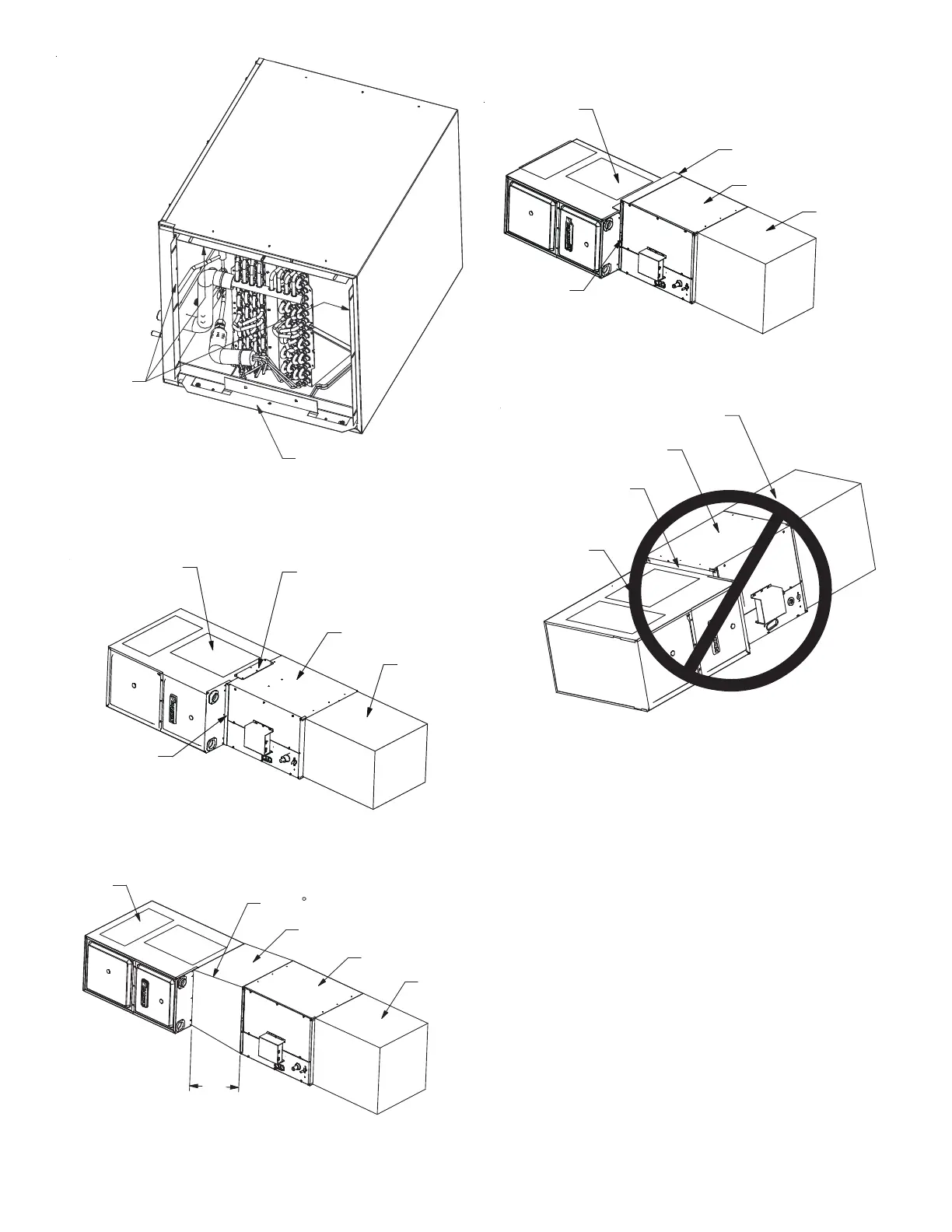
BOTTOM DUCT FLANG
E
FLANGE SIDE
Figure 4
4. Using the hardware and brackets provided, attach the coil to
the furnace then attach the plenum to the coil (Figure 5A-5C)
FURNACE
TIE-IN PLATES
(ACCESSO
RY)
COIL
PLENUM
L BRACKET
(ACCESSO
RY)
Figure 5A
18"
MINIMUM
FURNACE
MAX 10 ANGLE
TRANSITION
PLENUM
COIL
Figure 5B
(Z-BRACKET WITH NARROW FURNACE)
FURNACEF
Z BRACKET
(ACCESSO
RY)
COIL
C
PLENUM
L BRACKET
(ACCESSO
RY)
Figure 5C
FURNACE
DUCT BOARD SHEET
M
ETAL OR
OTH
ER
FILLER MATERIAL
COIL
PLENUM
Figure 5D
Incorrect Furnace, Coil and Plenum Installation
7 RETURN DUCTWORK
Do not locate the return ductwork in an area that can introduce
toxic or objectionable fumes/ordors into the ductwork.
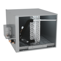
8 REFRIGERANT PIPING WORK
IMPORTANT NOTE: Do not handle coil assembly with manifold
liquid tubes or flowrator tubes. Doing so may result in damage to
the tubing joints. Always use clean gloves for handling coil assem-
blies.
8.1 Tubing Size/Length
Give special consideration to minimizing the length of refrigerant
tubing when installing cased coil. Refer to outdoor unit INSTALLA-
TION & SERVICE REFERENCE for line set configuration guidelines.
If possible, allow adequate length of tubing, so that the coil may be
removed (for inspection or cleaning services) from the cabinet
without disconnecting the tubing.
 Loading...