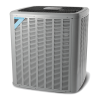
Do you have a question about the Daikin ComfortNet DX16TC0601AA and is the answer not in the manual?
Provides essential safety guidelines for handling refrigerants.
Guides users on identifying and understanding safety symbols and warnings.
Details how to measure system voltage and test for correct voltage levels.
Guides on troubleshooting the ComfortNet system's network communication using LEDs and buttons.
Lists and explains the conditions indicated by the 7-segment LED display codes.
Explains error codes and troubleshooting steps for air handler diagnostic codes.
Details how to test the transformer and its control circuit for proper operation.
Explains the diagnostic features integrated into the Comfort Alert™ unitary control.
Lists diagnostic codes, symptoms, causes, and corrective actions for system faults.
Continues the diagnostic code reference for various system fault conditions.
Explains how to test the high-pressure control for proper cutout pressure.
Explains the use of the diagnostic tool for ECM motor troubleshooting.
Explains how to set ECM CFM using dipswitches for DVPTC/MBVC models.
Provides warnings and procedures for checking compressor terminal venting safety.
Explains how to check the reversing valve for sticking and test its solenoid.
Details how to test outdoor air and coil temperature sensors for accuracy.
Explains how to troubleshoot data line voltages and bias switch settings for communication.
Explains how to test the limit control for heater elements to prevent overheating.
Describes methods for leak testing refrigeration systems using nitrogen.
Provides detailed instructions for charging the system with refrigerant, including safety precautions.
Details how to check compressor efficiency by examining operating parameters.
Explains how to check and calculate subcooling for refrigerant charge verification.
Explains how to diagnose and address compressor burnout conditions and system cleaning.
Details LED codes, possible causes, and corrective actions for network issues.
Details how to test the low-pressure control for proper cut-out and cut-in points.
Covers general checks and considerations for diagnosing Emerson Ultratech ECM motors.
Explains how to test compressor windings for resistance and continuity.
Guides on testing the defrost control sequence and related components.
Explains the process of evacuating the system to remove moisture and non-condensables.
Guides on setting airflow based on model, heater size, and trim adjustments.
Guides on performing a ground test for the compressor and related circuits.
Outlines essential practices and safety precautions for repairing refrigeration systems.
Guides on checking and adjusting superheat levels for proper system operation.
| Model | DX16TC0601AA |
|---|---|
| Type | Split System Air Conditioner |
| SEER Rating | 16 |
| EER | 12.5 |
| Refrigerant | R-410A |
| Compressor Type | Scroll |
| Sound Level | 74 dB |
| Voltage | 208/230 V |
| Phase | 1 |
| Frequency | 60 Hz |
| Sound Level (Outdoor Unit) | 74 dB |
| Cooling Capacity | 5 tons |


 Loading...