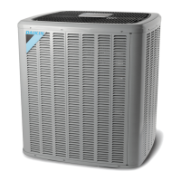
Do you have a question about the Daikin ComfortNet DX18TC0601AA and is the answer not in the manual?
Recognize safety symbols, words, and labels for safe operation and maintenance.
Guidelines for safe refrigerant handling, including breathing hazards and frostbite prevention.
Details on the defrost cycle control, timing, and operation for ComfortNet™ models.
Procedure for checking voltage at various points in the system, including locked rotor voltage.
Procedure to check the transformer's primary and secondary voltage for proper operation.
Procedure to measure high and low voltage supplied to the ECM motor and check fan relay contacts.
Introduction to Copeland Comfort Alert™ diagnostics integrated into the UC control for fault monitoring.
Procedure to check the high pressure control cutout pressure and continuity.
Instructions for using the Emerson UltraCheck-EZ™ tool to diagnose ECM motors.
Safety warnings and procedures for checking compressor terminal venting and physical integrity.
Procedure to check outdoor air and coil temperature sensors for resistance and proper function.
Procedure to check the continuity of heater limit controls.
Procedure for leak testing the system using dry nitrogen and soapy water or a leak detector.
Instructions for charging the system with refrigerant, including subcooling and superheat adjustments.
Method to check compressor efficiency by analyzing scroll flank condition and performance tests.
Procedure for checking refrigerant subcooling using pressure and temperature readings.
Method to check compressor efficiency by analyzing scroll flank condition and performance tests.
Procedure for diagnosing compressor burnout, analyzing oil samples, and cleaning the system.
Steps for visually inspecting and testing wiring for damage, shorts, and loose connections.
Procedure to check the low pressure control cutout and cutout/cut-in pressures.
General checks and considerations for diagnosing Emerson Ultratech™ ECM motors.
Procedure for testing compressor winding resistance and internal overload.
Procedure to check the continuity of the optional electric heater fuse link.
Procedure for evacuating the system to achieve a proper vacuum, including micron readings.
Procedure for checking for ground faults in the compressor circuit.
Instructions for visually inspecting and testing heater elements for continuity.
General practices and safety precautions for repairing refrigeration systems.
Explanation of superheat and procedures for checking and adjusting it.
Detailed steps and formulas for measuring refrigerant superheat.
| Model | DX18TC0601AA |
|---|---|
| SEER Rating | 18 |
| Refrigerant | R-410A |
| Energy Star Certified | Yes |
| Stages | Variable Speed |
| Voltage (V) | 208/230 |
| Phase | 1 |
| Frequency (Hz) | 60 |
| Type | Air Conditioner |
| Cooling Capacity | 60000 BTU |
| HSPF Rating | Not Applicable |


 Loading...