19
Fault Recall This feature allows the service person to check
for any fault history. The board memory is capable of re-
cording and storing 10 fault codes. To use this feature, the
furnace must not have an existing thermostat call. Pres-
sure fault recall button from 2-5 seconds (until the display
goes blank) then release, all faults will be displayed one at
a time, beginning with the most recent, max of 3 consecu-
tive faults will be stored. When all errors have been dis-
played the display returns to ON. To erase stored faults,
hold the fault recall button until the display starts flashing,
then release.
T
O
PREVENT
POSSIBLE
EQUIPMENT
DAMAGE
,
PROPERTY
DAMAGE
,
PERSONAL
INJURY
OR
DEATH
,
THE
FOLLOWING
BULLET
POINTS
MUST
BE
OBSERVED
WHEN
INSTALLING
THIS
UNIT
.
WARNING
P
OSSIBLE
PROPERTY
DAMAGE
,
PERSONAL
INJURY
OR
DEATH
DUE
TO
FIRE
,
EXPLOSION
,
SMOKE
,
SOOT
,
CONDENSATION
,
ELECTRICAL
SHOCK
OR
CARBON
MONOXIDE
MAY
RESULT
FROM
IMPROPER
INSTALLATION
,
REPAIR
OPERATION
,
OR
MAINTENANCE
OF
THIS
PRODUCT
.
WARNING
CLEARANCES AND ACCESSIBILITY
POSITION* FRONT SIDES REAR TOP FLUE FLOOR
Upflow 3" 0" 0" 1" 0" C
Horizontal Alcove 6" 0" 4" 0" C
C = If placed on combustible floor, floor MUST be wood only.
DM97C MINIMUM CLEARANCES TO COMBUSTIBLE MATERIALS
(INCHES)
NOTES:
• For servicing or cleaning, a 24” front clearance is required.
• Unit connections (electrical, flue and drain) may necessitate greater
clearances than the minimum clearances listed above.
• In all cases, accessibility clearance must take precedence over clearances
from the enclosure where accessibility clearances are greater.
POSITION* SIDES REAR FRONT BOTTOM FLUE TOP
Counterflow 0" 0" 3" NC 0"
Horizontal 6" 0" 3" C 0" 6"
C = If placed on combustible floor, floor MUST be wood only.
NC = For installation on non-combustible floors only. A combustible subbase
must
e use
or insta
ations on com
usti
e
ooring.
DC97MC MINIMUM CLEARANCES TO COMBUSTIBLE MATERIALS
(INCHES)
NOTES:
• For servicing or cleaning, a 24” front clearance is required.
• Unit connections (electrical, flue and drain) may necessitate greater
clearances than the minimum clearances listed above.
• In all cases, accessibility clearance must take precedence over clearances
from the enclosure where accessibility clearances are greater.
Installations must adhere to the clearances to combustible ma-
terials to which this furnace has been design certified. The
minimum clearance information for this furnace is provided on
the unit’s clearance label. These clearances must be perma-
nently maintained. Clearances must also accommodate an
installation’s gas, electrical, and drain trap and drain line con-
nections. If the alternate combustion air intake or vent/flue
connections are used additional clearance must be provided to
accommodate these connections. Refer to Vent/Flue Pipe and
Combustion Air Pipe for details. NOTE: In addition to the
required clearances to combustible materials, a minimum of 24
inches service clearance must be available in front of the unit.
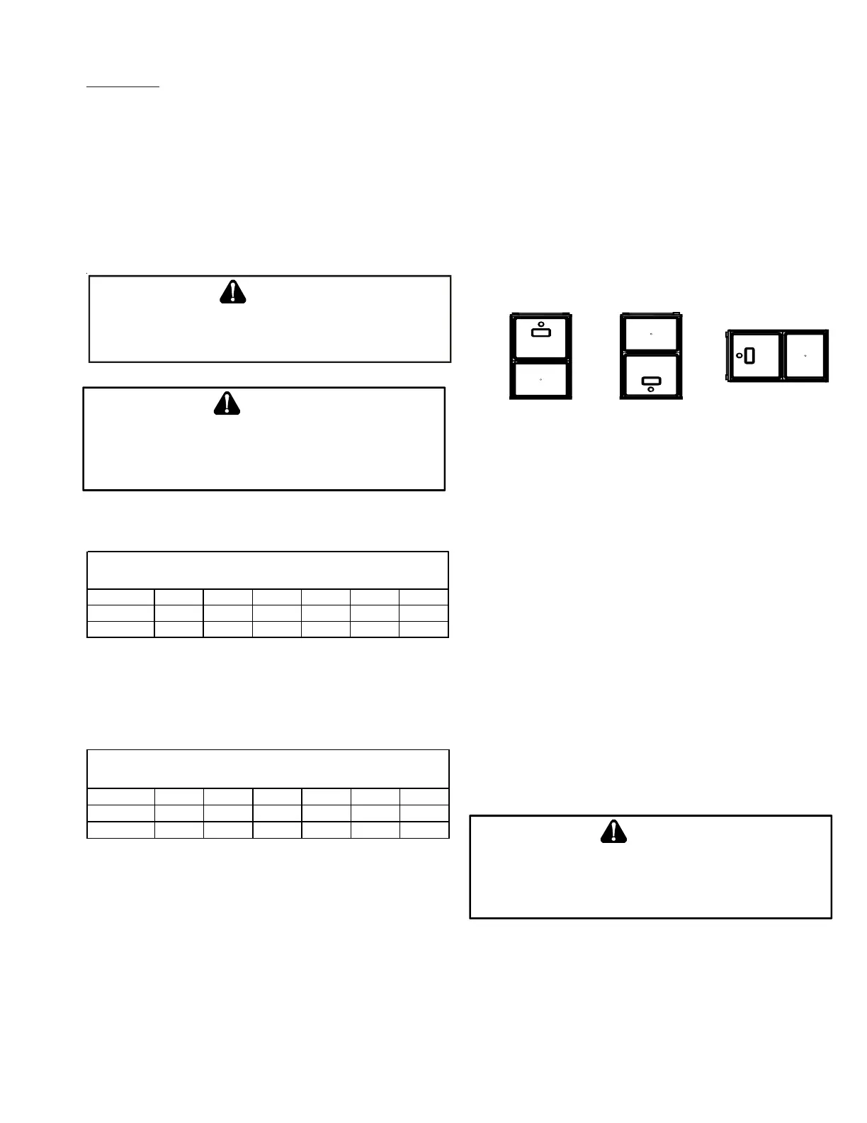
TOP
BOTTOM
SIDE SIDE SIDE
TOP
BOTTOM
Upflow Counterflow Horizontal
THERMOSTAT LOCATION
The thermostat should be placed approximately five feet from
the floor on a vibration-free, inside wall in an area having
good air circulation. Do not install the thermostat where it
may be influenced by any of the following:
• Drafts, or dead spots behind doors, in corners, or under
cabinets.
• Hot or cold air from registers.
• Radiant heat from the sun.
• Light fixtures or other appliances.
• Radiant heat from a fireplace.
• Concealed hot or cold water pipes, or chimneys.
• Unconditioned areas behind the thermostat, such as an
outside wall.
Consult the instructions packaged with the thermostat for
mounting instructions and further precautions.
Combustion & Ventilation Air Requirements
T
O
AVOID
PROPERTY
DAMAGE
,
PERSONAL
INJURY
OR
DEATH
,
SUFFICIENT
FRESH
AIR
FOR
PROPER
COMBUSTION
AND
VENTILATION
OF
FLUE
GASES
MUST
BE
SUPPLIED
. M
OST
HOMES
REQUIRE
OUTSIDE
AIR
BE
SUPPLIED
INTO
THE
FURNACE
AREA
.
WARNING
PRODUCT DESIGN