22
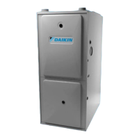
PREFERRED
TRANSITION NO LESS
THAN 45 DEGREES TO
HORIZONTAL PLANE TO
AVOID CREATING A WATER
TRAP IN VENT PIPING.
ACCEPTABLE
NO TRANSITION ON
HORIZONTAL PLANE,
THIS CREATES A
WATER TRAP AND
RESTRICTS FLUE
GASES
PRODUCT DESIGN
12345678
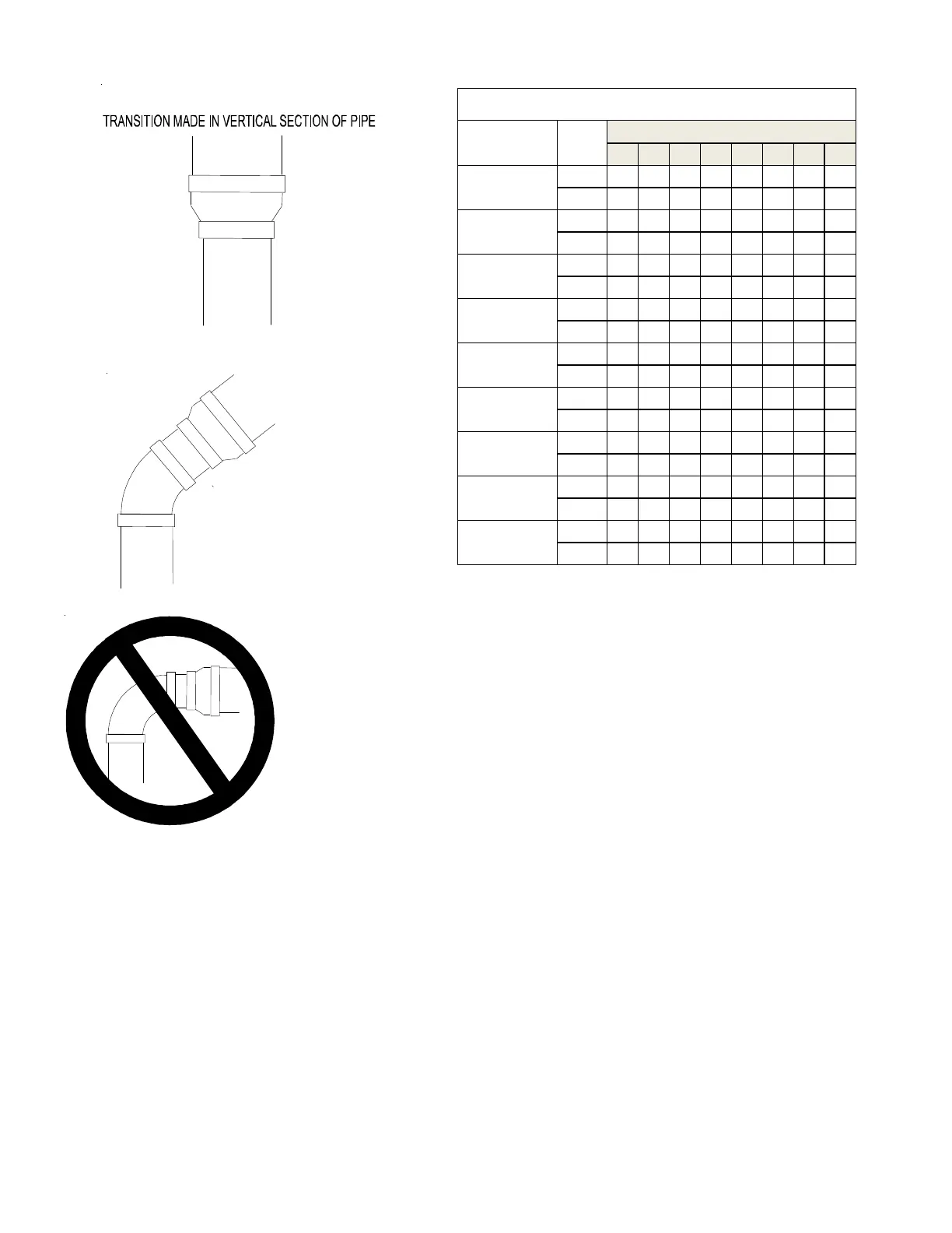
2 or 2 1/2
115 110 105 100 95 90 85 80
3
137 130 123 116 109 102 95 88
2 or 2 1/2
115 110 105 100 95 90 85 80
3
147 140 133 126 119 112 105 98
2 or 2 1/2
60 55 50 45 40 35 30 25
3
120 113 106 99 92 85 78 71
2 or 2 1/2
40 35 30 25 20 15 10 5
3
144 137 130 123 116 109 102 95
2 or 2 1/2
40 35 30 25 20 15 10 5
3
144 137 130 123 116 109 102 95
2 or 2 1/2
95 90 85 80 75 70 65 60
3
144 137 130 123 116 109 102 95
2 or 2 1/2
95 90 85 80 75 70 65 60
3
144 137 130 123 116 109 102 95
2 or 2 1/2
60 55 50 45 40 35 30 25
3
120 113 106 99 92 85 78 71
2 or 2 1/2
40 35 30 25 20 15 10 5
3
103 96 89 82 75 68 61 54
DC97MC1005CNA*
DM97MC0804CNA*
DM97MC1005CNA*
DM97MC1205DNA*
DC97MC0603BNA*
DC97MC0803BNA*
DC97MC0804CNA*
DM97MC0803BNA*
Direct Vent (2 - Pipe) and Non-Direct Vent (1- Pipe)
(6)
Model Pipe Size
Number of Elbows
DM97MC0603BNA*
1) Maximum allowable limits listed on individual lengths for inlet and
flue and NOT a combination.
2) Minimum requirement for each vent pipe is five (5) feet in length
and one elbow/tee.
3) Tee used in the vent/flue termination must be included when de-
termining the number of elbows in the piping system.
4) 2 1/2” or 3” diameter pipe can be used in place of 2” diameter
pipe.
5) Increased Clearance Configurations using (2) 45 deg.
elbows should
be considered equivalent to one 90 deg. elbow.
6) One 90° elbow should be secured to the combustion air intake
connection.
7) For installations at or above 7,000 feet altitude, use 3” venting.