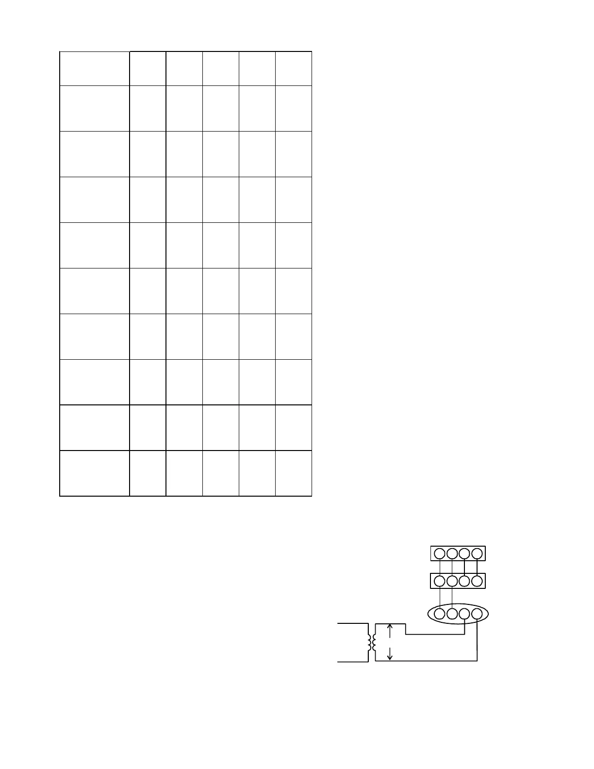
43
Model Tap
Low
Stage
Cool
High
Stage
Cool
Low
Stage
Heat
High
Stage
Heat
A
398 599 667 953
B
557 817 740 1059
C
696 1007 808 1158
D
810 1212 881 1260
A
403 629 855 1202
B
540 806 923 1316
C
705 1023 1033 1389
D
819 1230 1063 1396
A
513 789 867 1228
B
660 967 939 1337
C
791 1182 1016 1430
D
913 1375 1077 1516
A
564 820 1256 1818
B
784 1133 1292 1870
C
982 1464 1316 1910
D
1259 1736 1358 1957
A
547 867 1329 1891
B
831 1160 1362 1940
C
1020 1467 1390 1968
D
1278 1910 1440 2028
A
433 656 687 938
B
541 790 751 950
C
686 972 814 986
D
806 1195 874 992
A 405 624 758 1057
B 549 808 815 1146
C 678 994 882 1256
D 784 1177 946 1349
A
556 837 889 1234
B
714 1022 944 1325
C
838 1206 1019 1442
D
991 1475 1068 1528
A
524 784 1209 1759
B
744 1078 1249 1797
C
927 1388 1277 1840
D
1185 1766 1300 1881
DM97MC0603BN**
DM97MC0803BN**
DM97MC0804CN**
DM97MC1005CN**
DM97MC1205DN**
DC97MC0603BN**
DC97MC0803BN**
DC97MC0804CN**
DC97MC1005CN**
Airflow Table
BLOWER HEAT OFF DELAY TIMINGS
The integrated control module provides a selectable heat off
delay function. The heat off delay period may be set to 90, 120,
150, 180 seconds using the DIP switches or jumper provided on
the control module. The delay is factory shipped at 150 seconds
but may be changed to suit the installation requirements and/
or homeowner preference.
ComfortNet System
OVERVIEW
NOTE: DIP switch #13 MUST be set to match thermostat
type. To use the CTK01 communicating thermostat, DIP
switch #13 must be set to ON position. This is also the
correct setting for a non-communicating 2-stage thermo-
stat. To use the CTK02**, CTK03 & CTK04 modulating ther-
mostat, check to make sure DIP switch #13 is in the OFF
position (factory position). This is also the correct position
when using a non-communicating single stage thermostat.
The ComfortNet system is a system that includes a ComfortNet
compatible furnace and air conditioner or heat pump with a
CTK0* thermostat. A valid ComfortNet system could also be a
compatible furnace, CTK0* communicating, single stage air
conditioner. Any other system configurations are considered
invalid ComfortNet systems and must be connected as a tradi-
tional (or non-communicating) system (see Electrical Connec-
tions for wiring connections).
A ComfortNet heating/air conditioning system differs from a
non-communicating/traditional system in the manner in which
the indoor unit, outdoor unit and thermostat interact with one
another. In a traditional system, the thermostat sends com-
mands to the indoor and outdoor units via analog 24 VAC sig-
nals. It is a one-way communication path in that the indoor and
outdoor units typically do not return information to the thermo-
stat.
The indoor unit, outdoor unit and thermostat comprising a
ComfortNet system “communicate” digitally with one another,
creating a two-way communications path. The thermostat still
sends commands to the indoor and outdoor units. However,
the thermostat may also request and receive information from
both the indoor and outdoor units. This information may be
displayed on the ComfortNet thermostat. The indoor and out-
door units also interact with one another. The outdoor unit may
send commands to or request information from the indoor unit.
This two-way digital communications between the thermostat
and subsystems (indoor/outdoor unit) and between subsystems
is the key to unlocking the benefits and features of the
ComfortNet system.
12RC
12
RC
CTK0*
Thermostat
ComfortNet Compatible
Furnace Integrated
Control Module
ComfortNet Compatible
AC/HP Integrated
Control Module
40VA Transformer
208/230 VAC
24 VAC
12RC
System Wiring using Two-Wires between Furnace and AC/HP and
Four-Wires between Furnace and Thermostat
OPERATION